


SECTION 4. EXTERNAL STORAGE PERIPHERALS
4-2
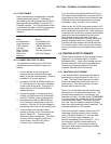
Instruction 96 has a single parameter which
specifies the peripheral to send output to.
Table 4.1-1 lists the output device codes.
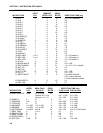
TABLE 4.1-1. Output Device Codes for
Instruction 96 and *8 Mode
Code Device
00 Tape. Data transferred in blocks of
512 Final Storage locations
09 Tape. All data since last output.
[Inst. 96 only]
ADDRESSED PRINTER
1x Printable ASCII
2x Comma delineated ASCII
3x Binary
PIN ENABLED PRINTER
4x Printable ASCII
5x Comma delineated ASCII
6x Binary
x = BAUD RATE CODES
0 300
1 1200
2 9600
3 76,800
7N Storage Module N (N=address, 1...8)
7N-- Output File Mark to Storage Module N
80 To the other Final Storage Area
[Inst. 96 only], new data since last
output
81 To the other Final Storage Area
[Inst. 96 only], entire active Final
Storage Area
The source of data for Instruction 96 is the
currently active Final Storage Area as set by
Instruction 80 (the default is Final Storage Area
1 at the beginning of each program table
execution).
If the CR10 is using the 9 pin connector for
other I/O tasks when Instruction 96 is executed,
the output request is put in a queue and
program execution continues. As the 9-pin
connector becomes available, each device in
the queue gets its turn.
An output request is not put in the queue if the
same device is already in the queue. The data
contained in the queue (and which determine a
unique entry) are the device, baud rate (if
applicable), and the Final Storage Area.
When an entry reaches the top of the queue,
the CR10 sends all data accumulated since the
last transfer to the device up to the location of
the DSP at the time the device became active.
The most efficient use of cassette tape and
power is made with the CASSETTE TAPE
option to transfer data in blocks of 512 Final
Storage locations. (Data is always written in
the equivalent of 512 locations. If code 09 was
used, and there are only 10 new values,
sending this data would include 502 null
characters.)
Option 09, transfer any new data, is used if it is
desired to run the tape only at particular times
or under certain conditions (the program is
written so that 96 only gets executed when
these conditions are met). When 96 finally
does get executed, all data between the TPTR
and DSP, including a final block less than 512
locations, are written to tape.
Section 4.3 contains specifics on the cassette
recorder. Note that tape operation is for above
freezing temperatures only.
Printer output can be either pin-enabled or
addressed. However, there is not a pin
specifically dedicated to print enable. When a
pin-enabled print output is specified, the SDE
line, which is normally used in the addressing
sequence, is used as a print enable. This
allows some compatibility with the CR21, 21X,
and CR7 dataloggers which have a Print
Enable line. The pin-enabled print option will
result in garbage being sent to the print
peripheral if an addressed device is also
connected to the CR10 (i.e., CR10KD, SM192
or SM716 etc.). The SDC99 Synchronous
Device Interface can convert a print device to
an Addressed peripheral (Section 6.2).
The STORAGE MODULE address is important
only when using more than one Storage
Module, 1 is a universal address which will find
the Storage Module with lowest number
address that is connected. If a Storage Module
is not connected, the CR10 will not advance the
SPTR (Section 2.1) and the Storage Module
drops out of the queue until the next time
Instruction 96 is executed. Section 4.5 contains
specifics on the SM192 and SM716.