


SECTION 13. CR10 MEASUREMENTS
13-6
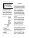
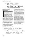
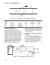
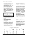
FIGURE 13.3-4. Wire Manufacturers Capacitance Specifications, C
w
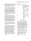
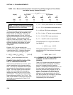
TABLE 13.3-2. Properties of Three Belden Lead Wires Used by Campbell Scientific
Belden Rl C
w
Wire # Conductors Insulation AWG (ohms/1000ft.) (pfd/ft.)
8641 1 shld. pair polyethylene 24 23 42
8771 1 shld. 3 cond. polyethylene 22 15 41
8723 2 shld. pair polypropylene 22 15 62
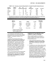
DIELECTRIC ABSORPTION
The dielectric absorption of insulation
surrounding individual conductors can seriously
affect the settling waveform by increasing the
time required to settle as compared to a simple
exponential. Dielectric absorption is difficult to
quantify, but it can have a serious effect on low
level measurements (i.e., 50 mV or less). The
primary rule to follow in minimizing dielectric
absorption is: Avoid PVC insulation around
conductors. PVC cable jackets are permissible
since the jackets don't contribute to the lead
capacitance because the jacket is outside the
shield. Campbell Scientific uses only
polyethylene and polypropylene insulated
conductors in CR10 sensors (see Table 13.3-2)
since these materials have negligible dielectric
absorption. Teflon insulation is also very good
but quite expensive.
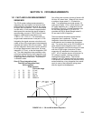
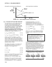
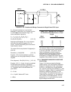
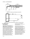
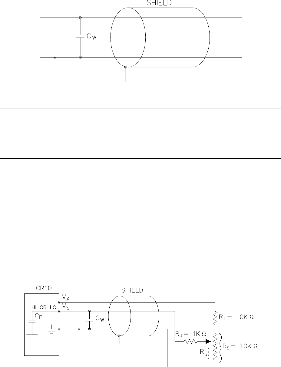
13.3.2 EFFECT OF LEAD LENGTH ON SIGNAL
RISE TIME
In the 024A Wind Vane, a potentiometer
sensor, the peak transient voltage is much less
than the true signal voltage (see Table 13.3-5).
This means the signal rise time is the major
source of error and the time constant is the
same as if C
w
were between the signal lead
and ground as represented below.
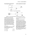
FIGURE 13.3-5. Model 024A Wind Direction Sensor