


SECTION 13. CR10 MEASUREMENTS
13-5
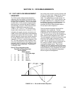
Before proceeding with examples of the effect
of long lead lengths on the measurement, a
discussion on obtaining the source resistance,
R
o
, and lead capacitance, C
w
L, is necessary.
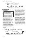
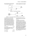
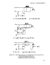
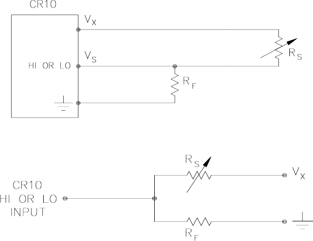
FIGURE 13.3-2. Typical Resistive Half Bridge
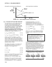
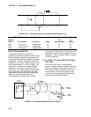
FIGURE 13.3-3. Source Resistance Model for Half Bridge Connected to the CR10
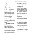
DETERMINING SOURCE RESISTANCE
The source resistance used to estimate the
settling time constant is the resistance the
CR10 input "sees" looking out at the sensor.
For our purposes the source resistance can be
defined as the resistance from the CR10 input
through all external paths back to the CR10.
Figure 13.3-2 shows a typical resistive sensor,
(e.g., a thermistor) configured as a half bridge.
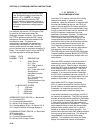
Figure 13.3-3 shows Figure 13.3-2 re-drawn in
terms of the resistive paths determining the
source resistance Ro, is given by the parallel
resistance of Rs and Rf, as shown in Equation
13.3-8.
R
o
= R
s
R
f
/(R
s
+R
f
) [13.3-8]
If R
f
is much smaller, equal to or much greater
than R
s
, the source resistance can be
approximated by Equations 13.3-9 through
13.3-11, respectively.
R
o
~ R
f
, R
f
<<R
s
[13.3-9]
R
o
= R
f
/2, R
f
=R
s
[13.3-10]
R
o
~ R
s
, R
f
>>R
s
[13.3-11]
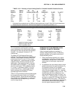
The source resistance for several Campbell
Scientific sensors are given in column 3 of
Table 13.3-5.
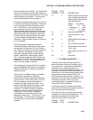
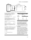
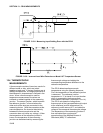
DETERMINING LEAD CAPACITANCE
Wire manufacturers typically provide two
capacitance specifications: 1) the capacitance
between the two leads with the shield floating,
and 2) the capacitance between the two leads
with the shield tied to one lead. Since the input
lead and the shield are tied to ground (often
through a bridge resistor, R
f
) in single-ended
measurements such as Figure 13.3-2, the
second specification is used in determining lead
capacitance. Figure 13.3-4 is a representation
of this capacitance, C
w
, usually specified as
pfd/ft. C
w
is actually the sum of capacitance
between the two conductors and the
capacitance between the top conductor and the
shield. Capacitance for 3 Belden lead wires
used in Campbell Scientific sensors is shown in
column 6 of Table 13.3-2.