


SECTION 13. CR10 MEASUREMENTS
13-8
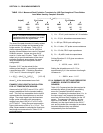
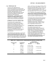
TABLE 13.3-4. Measured Peak Excitation Transients for 1000 Foot Lengths of Three Belden
Lead Wires Used by Campbell Scientific
-----------------------V
eo
(mV) -----------------------
Vx(mV) R
f
=1 kohm R
f
=10 kohm
### # ##
8641 8771 8723 8641 8771 8723
2000 50 100 60 100 140 80
1000 25 65 40 60 90 40
NOTE: Excitation transients are eliminated
if excitation leads are contained in a shield
independent from the signal leads.
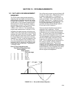
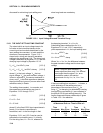
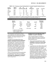
The size of the peak transient is linearly related
to the excitation voltage and increases as the
bridge resistor, R
f
, increases. Table 13.3-4
shows measured levels of V
eo
for 1000 foot
lengths of three Belden wires used in Campbell
Scientific sensors. Values are given for R
f
equal to 1 kohm and 10 kohm. Table 13.3-4 is
meant only to provide estimates of the size of
excitation transients encountered; the exact
level will depend upon the specific sensor
configuration.
Equation 13.3-7 can be solved for the
maximum lead length, L, permitted to maintain
a specified error limit. Combining Equations
13.3-7 and 13.3-4 and solving for L gives:
L = -(R
o
C
f
+ (t/ln(V
e
/V
eo
)))/R
o
C
w
[13.3-15]
where V
e
is the measurement error limit.
EXAMPLE LEAD LENGTH CALCULATION
FOR 107 TEMPERATURE SENSOR
Assume a limit of 0.05°C over a 0°C to +40°C
range is established for the transient settling
error. This limit is a reasonable choice since it
approximates the linearization error over that
range. The output signal from the thermistor
bridge varies nonlinearly with temperature
ranging from about 100 µV/=°C at 0°C to 50
µV/°C at 40°C. Taking the most conservative
figure yields an error limit of V
e
= 2.5 µV. The
other values needed to calculate the maximum
lead length are summarized in Table 13.3-5
and listed below:
1) V
eo
~ 50 mV, peak transient at 2 V excitation
2) V
e
~ 2.5 µV, allowable measurement error
3) t = 450 µs, CR10 input settling time
4) R
o
= 1 kohm, 107 probe source resistance
5) C
f
= 3.3 nfd, CR10 input capacitance
6) C
w
~ 42 pfd/ft., lead wire capacitance
Solving Equation 13.3-15 gives a maximum
lead length of:
L ~ 1003 ft., error ~ 0.05°C
Setting the allowable error at 0.1°C or
approximately 5 µV, the maximum lead length
increases to:
L ~ 1085 ft., error ~ 0.1°C
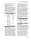
13.3.4 SUMMARY OF SETTLING ERRORS FOR
CAMPBELL SCIENTIFIC RESISTIVE
SENSORS
Table 13.3-5 summarizes the data required to
estimate the effect of lead length on settling
errors for Campbell Scientific's resistive
sensors. Comparing the transient level, V
eo
, to
the input range, one suspects that transient
errors are the most likely limitation for the 107
sensor. The sensors in the WVU-7 are the
same as in the Model 107 (the lead wire is
different), but the signal leads for the WVU-7
wet- and dry-bulbs are not subject to excitation
transients because they are shielded
independently from the excitation.