


SECTION 9. INPUT/OUTPUT INSTRUCTIONS
9-8
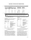
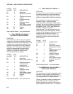
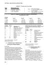
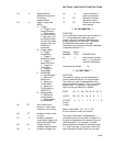
TABLE 9-3. Thermocouple Type Codes
Code Thermocouple Type
X1 T (copper - constantan) X = 0 Normal Measurement
X2 E (chromel - constantan) X = 8 TC input from A5B40 isolation
X3 K (chromel - alumel) (uses 5 V range)
X4 J (iron - constantan) X = 9 Output -99999 if out of common
mode range (Inst. 14 only)
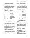
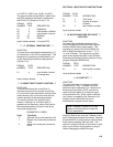
TABLE 9-4. Voltage and Temperature Ranges for Thermocouples
if the Reference is 20°C
Voltage
Range Type T Type E Type K Type J
±2.5 mV -46 to 50 -21 to 60 -44 to 80 -29 to 67
±7.5 mV -270 to 181 -124 to 134 -270 to 620 -149 to 159
±25 mV -270 to 400 -270 to 365 -270 to 620 -210 to 476
±250 mV −−− -270 to 1000 -270 to 1372 -210 to 760
PARAM. DATA
NUMBER TYPE DESCRIPTION
01: 2 Repetitions
02: 2 Range code (Table 9-4)
03: 2 Single-ended channel
number for first TC
04: 2 Thermocouple type
code
05: 4 Reference temperature
location
06: 4 Destination input
location
07: FP Multiplier
08: FP Offset
Input locations altered: 1 for each
thermocouple channel
*** 14 THERMOCOUPLE TEMPERATURE,
***
DIFFERENTIAL MEASUREMENT
FUNCTION
This instruction calculates the thermocouple
temperature for the thermocouple type selected.
The instruction specifies a DIFFERENTIAL
VOLTAGE MEASUREMENT (Section 13.2) on
the thermocouple, adds the measured voltage to
the voltage calculated for the reference
temperature relative to 0°C, and converts the
combined voltage to temperature in °C. The
differential inputs are briefly shorted to ground
prior to making the voltage measurement to
insure that they are within the common mode
range. Table 9-3 gives the thermocouple type
codes for Parameter 4. Enter a 9 in front of the
code and the CR10 will make an additional
check on common mode range; -99999 is output
for temperature if common mode range is
exceeded.
PARAM. DATA
NUMBER TYPE DESCRIPTION
01: 2 Repetitions
02: 2 Range code (Table 9-1)
03: 2 Differential channel
number for first TC
04: 2 Thermocouple type
code
05: 4 Reference temperature
location
06: 4 Destination input
location
07: FP Multiplier
08: FP Offset
Input locations altered: 1 for each
thermocouple channel
*** 16 TEMPERATURE FROM ***
PLATINUM R.T.D.
FUNCTION
This instruction uses the result of a previous
RTD bridge measurement to calculate the
temperature according to the DIN 43760
specification adjusted (1980) to conform to the
International Electrotechnical Commission
standard. The range of linearization is -200° to
850°C. The error in the linearization is less
than 0.001°C between -100° and +300°C, and
is less than 0.003°C between -180° and
+830°C. The error (T calculated - T standard)