


CR10 OVERVIEW
OV-6
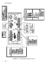
OV1.1.1 ANALOG INPUTS
The terminals labeled 1H to 6L are analog
inputs. These numbers refer to the high and
low inputs to the differential channels 1 through
6. In a differential measurement, the voltage on
the H input is measured with respect to the
voltage on the L input. When making single-
ended measurements, either the H or L input
may be used as an independent channel to
measure voltage with respect to the CR10
analog ground (AG). The single-ended
channels are numbered sequentially starting
with 1H; e.g., the H and L sides of differential
channel 1 are single-ended channels 1 and 2;
the H and L sides of differential channel 2 are
single-ended channels 3 and 4, etc. (The
single-ended channel numbers do NOT appear
on older wiring panels).
OV1.1.2 SWITCHED EXCITATION OUTPUTS
The terminals labeled E1, E2, and E3 are
precision, switched excitation outputs used to
supply programmable excitation voltages for
resistive bridge measurements. DC or AC
excitation at voltages between -2500 mV and
+2500 mV are user programmable (Section 9).
OV1.1.3 PULSE INPUTS
The terminals labeled P1 and P2 are the pulse
counter inputs for the CR10. They are
programmable for switch closure, high
frequency pulse or low level AC (Section 9,
Instruction 3).
OV1.1.4 DIGITAL I/O PORTS
Terminals C1 through C8 are digital
Input/Output ports. On power-up they are
configured as input ports, commonly used for
reading the status of an external signal. High
and low conditions are: 3V < high < 5.5V; -0.5V
< low < 0.8V.
Configured as outputs the ports allow on/off
control of external devices. A port can be set
high (5V ± 0.1V), set low (<0.1V), toggled or
pulsed (Sections 3, 8.3, and 12).
OV1.1.5 ANALOG GROUND (AG)
The AG terminals are analog grounds, used as
the reference for single-ended measurements
and excitation return.
OV1.1.6 12V AND POWER GROUND (G)
TERMINALS
The 12V and power ground (G) terminals are
used to supply 12V DC power to the
datalogger. The extra 12V and G terminals can
be used to connect other devices requiring 12V
power.
The G terminals are also used to tie cable
shields to ground, and to provide a ground
reference for pulse counters and binary inputs.
For protection against transient voltage spikes,
power ground should be connected to a good
earth ground (Section 14.3.1).
OV1.1.7 5V OUTPUTS
The two 5V (±0.2%) outputs are commonly
used to power peripherals such as the QD1
Incremental Encoder Interface, AVW1 or AVW4
Vibrating Wire Interface.
The 5V outputs are common with pin 1 on the 9
pin serial connector; 200 mA is the maximum
combined output.
OV1.1.8 SERIAL I/O
The 9 pin serial I/O port contains lines for serial
communication between the CR10 and external
devices such as computers, printers, Storage
Modules, etc. This port does NOT have the
same configuration as the 9 pin serial ports
currently used on many personal computers.
It has a 5VDC power line which is used to power
peripherals such as the SM192 or SM716
Storage Module or the DC112 Phone Modem.
The same 5VDC supply is used for the 5V
outputs on the lower terminal strip. Section 6
contains technical details on serial
communication.
OV1.1.9 SWITCHED 12 VOLT
Wiring panels introduced in March 1994 include
a switched 12 volt output. This can be used to
power sensors or devices requiring an
unregulated 12 volts. The output is limited to
600 mA current.
A control port is used to operate the switch.
Connect a wire from the control port to the
switched 12 volt control port. When the port is
set high, the 12 volts is turned on; when the
port is low, the switched 12 volts is off.