


SECTION 14. INSTALLATION AND MAINTENANCE
14-8
14.7 GROUNDING
14.7.1 PROTECTION FROM LIGHTNING
Primary lightning strikes are those where
lightning hits the datalogger or sensors directly.
Secondary strikes occur when the lightning
strikes somewhere near the system and
induces a voltage in the wires. The purpose of
an earth ground is to minimize damage to the
system by providing a low resistance path
around the system to a point of low potential.
Campbell Scientific recommends that all
dataloggers in use in the field be earth
grounded. All components of the system
(datalogger, sensors, external power supplies,
mounts, housings, etc.) should be referenced to
one common earth ground.
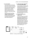
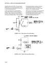
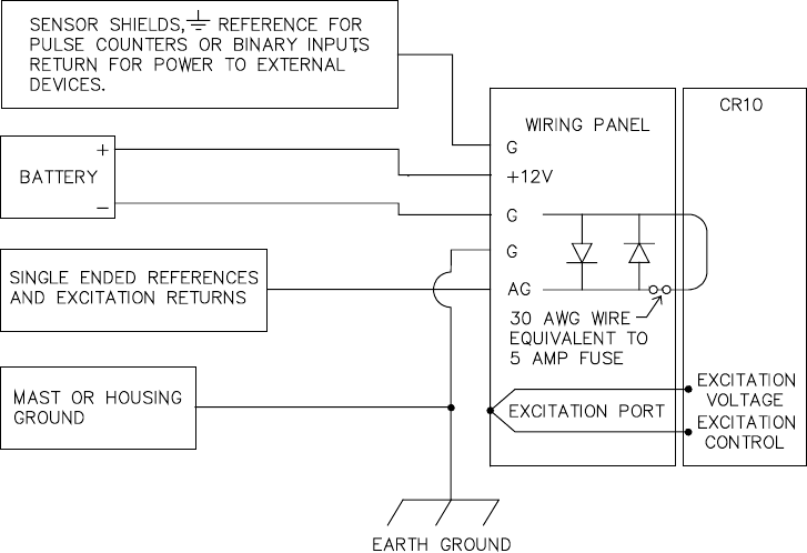
Every terminal on the Wiring Panel, with the
exception of ground (G) and analog ground
(AG) terminals are spark gapped. The spark
gaps will fire at 150 V and the current will be
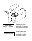
diverted to ground. As shown in Figure 14.7-1,
the power ground and analog ground are
independent lines until joined inside the CR10.
The fuse shown in Figure 14.7-1 (located on
the underside of the Wiring Panel) is a 30 AWG
wire, equivalent to a conventional 5 Amp fuse.
It will blow if a sufficient transient comes in on
the G or AG lines, at which time the current is
directed away from the CR10 through the
diodes. The fuse may be replaced by soldering
another 30 AWG wire to the soldering pads
provided.
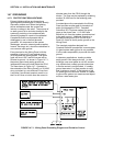
A modem/phone line connected to the Wiring
Panel provides another path for transients to
enter and damage the CR10. Campbell
Scientific's DC112 phone modem has spark
gaps on the phone lines. A 12 AWG wire
should be run from the modem ground terminal
to the earth ground. Additional protection is
provided by the ground (Pin 2) of the 9 pin
Serial I/O which is tied to power ground on the
Wiring Panel.
The transient protection designed into
Campbell Scientific's equipment is meaningless
if a good system earth ground is not provided.
It is the users responsibility to provide this earth
ground.
In laboratory applications, locating a stable
earth ground is not always obvious. In older
buildings, new cover plates on old AC sockets
may indicate that a safety ground exists when
in fact the socket is not grounded. If a safety
ground does exist, it is good practice to verify
that it carries no current. If the integrity of the
AC power ground cannot be verified, it is better
to ground the system to a massive metal object
such as a steel water pipe.
FIGURE 14.7-1. Wiring Panel Grounding Diagram and Excitation Control