


SECTION 7. MEASUREMENT PROGRAMMING EXAMPLES
7-14
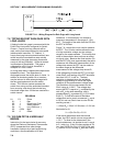
PROGRAM
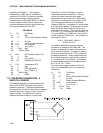
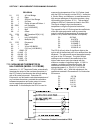
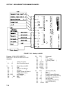
01: P5 AC Half Bridge
01: 6 Reps
02: 15 2500 mV fast Range
03: 1 IN Chan
04: 1 Excite all reps w/EXchan 1
05: 2500 mV Excitation
06: 1 Loc [:H20 BARS ]
07: 1 Mult
08: 0 Offset
02: P59 BR Transform Rf[X/(1-X)]
01: 6 Reps
02: 1 Loc [:H20 BARS ]
03: .1 Multiplier (Rf)
03: P55 Polynomial
01: 6 Reps
02: 1 X Loc H20 BARS
03: 1 F(X) Loc [:H20 BARS ]
04: .15836 C0
05: 6.1445 C1
06: -8.4189 C2
07: 9.2493 C3
08: -3.1685 C4
09: .33392 C5
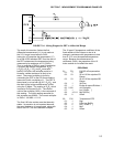
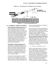
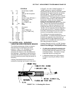
7.15 NONLINEAR THERMISTOR IN
HALF BRIDGE (MODEL 101 PROBE)
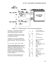
Instruction 11, 107 Thermistor Probe, automatically
linearizes the output of the nonlinear thermistor in
the 107 Probe by transforming the millivolt reading
with a 5th order polynomial. Instruction 55,
Polynomial, can be used to calculate temperature of
any nonlinear thermistor, provided the correlation
between temperature and probe output is known,
and an appropriate polynomial fit has been
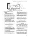
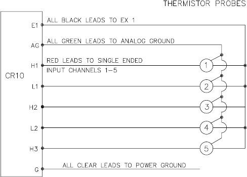
determined. In this example, the CR10 is used to
measure the temperature of five 101 Probes (used
with the CR21 but usually not the CR10). Instruction
4, Excite, Delay, and Measure, is used because the
high source resistance of the probe requires a long
input settling time (Section 12.3.1). The excitation
voltage is 2000 mV, the same as used in the CR21.
The signal voltage is then transformed to
temperature using the Polynomial Instruction.
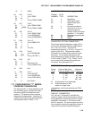
The manual for the 101 Probe gives the coefficients
of the 5th order polynomial used to convert the
output in millivolts to temperature (E denotes the
power of 10 by which the mantissa is multiplied):
C0 -53.7842
C1 0.147974
C2 -2.18755E-4
C3 2.19046E-7
C4 -1.11341E-10
C5 2.33651E-14
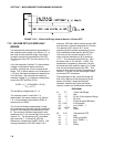
The CR10 will only allow 5 significant digits to the
right or left of the decimal point to be entered from the
keyboard. The polynomial cannot be applied exactly
as given in the 101 manual. The initial millivolt
reading must be scaled if the coefficients of the
higher order terms are to be entered with the
maximum number of significant digits. If 0.001 is
used as a multiplier on the millivolt output, the
coefficients are divided by 0.001 raised to the
appropriate power (i.e., C0=C0, C1=C1/0.001,
C2=C2/.000001, etc.). With this adjustment, the
coefficients entered in Parameters 4-9 of Instruction
55 become:
C0 -53.784
C1 147.97
C2 -218.76
C3 219.05
C4 -111.34
C5 23.365
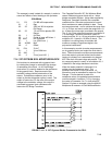
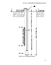
FIGURE 7.15-1. 101 Thermistor Probes Connected to CR10