


LIST OF FIGURES
LF-2
PAGE
8. PROCESSING AND PROGRAM CONTROL EXAMPLES
8.3-1 AM416 Wiring Diagram for Thermocouple and Soil Moisture Block Measurements ............ 8-4
8.5-1 Connections for Rain Gage.................................................................................................... 8-6
9. INPUT/OUTPUT INSTRUCTIONS
9-1 Conditioning for Long Duration Voltage Pulses..................................................................... 9-2
13. CR10 MEASUREMENTS
13.1-1 50 and 60 Hz Noise Rejection ............................................................................................. 13-1
13.2-1 Timing of Single-Ended Measurement ................................................................................ 13-2
13.2-2 Differential Voltage Measurement Sequence ...................................................................... 13-2
13.3-1 Input Voltage Rise and Transient Decay ............................................................................. 13-4
13.3-2 Typical Resistive Half Bridge ............................................................................................... 13-5
13.3-3 Source Resistance Model for Half Bridge Connected to the CR10..................................... 13-5
13.3-4 Wire Manufacturers Capacitance Specifications, Cw.......................................................... 13-6
13.3-5 Model 024A Wind Direction Sensor..................................................................................... 13-6
13.3-6 Resistive Half Bridge Connected to Single-Ended CR10 Input........................................... 13-7
13.3-7 Half Bridge Configuration for YSI #44032 Thermistor Connected to CR10 ...................... 13-11
13.3-8 Measuring Input Settling Error with the CR10 ................................................................... 13-12
13.3-9 Incorrect Lead Wire Extension on Model 107 Temperature Sensor ................................. 13-12
13.4-1 Thermistor Polynomial Error .............................................................................................. 13-14
13.4-2 Diagram of Junction Box.................................................................................................... 13-16
13.5-1 Circuits Used with Instructions 4-9 .................................................................................... 13-18
13.5-2 Excitation and Measurement Sequence for 4 Wire Full Bridge......................................... 13-19
13.6-1 AC Excitation and Measurement Sequence for AC Half Bridge........................................ 13-21
13.6-2 Model of Resistive Sensor with Ground Loop ................................................................... 13-21
14. INSTALLATION AND MAINTENANCE
14.3-1 PS12 12 Volt Power Supply and Charging Regulator ......................................................... 14-3
14.6-1 Connecting to Vehicle Power Supply................................................................................... 14-5
14.7-1 Wiring Panel Grounding Diagram and Excitation Control.................................................... 14-6
14.10-1 Relay Driver Circuit with Relay ............................................................................................ 14-8
14.10-2 Power Switching without Relay............................................................................................ 14-8
APPENDIX G. CHANGING RAM OR PROM CHIPS
G-1 Disassembling CR10 .............................................................................................................G-2
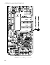
G-2 Jumper Settings for Different RAM Configurations................................................................G-2
G-3 Jumper Settings and Locations .............................................................................................G-3