


SECTION 9. INPUT/OUTPUT INSTRUCTIONS
9-16
of the measurement. An AVW1 or AVW4 Vibrating
Wire Interface is usually required for these sensors.
PARAM. DATA
NUMBER TYPE DESCRIPTION
01: 2 Repetitions Hit C (--) to
skip repeat of
excitation
02: 2 Single-ended channel
for first measurement
03: 2 Excitation Channel
04: 2 Start frequency of
sweep (100'S of Hz)
05: 2 End frequency of
sweep (100'S of Hz)
06: 4 # Cycles to measure (0
means none)
07: 4 Delay before excitation
applied (0.01 sec units)
08: 4 Input location (1/T
2
), T
in ms
09: FP Multiplier
10: FP Offset
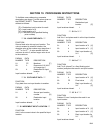
*** 101 SDM-INT8 ***
FUNCTION
The 8 channel Interval Timer (INT8) is a
measurement module which provides processed
timing information to the datalogger. Each of the 8
input channels may be independently configured
to detect either rising or falling edges of either a
low level AC signal of a 5 V logic signal. Each
channel may be independently programmed. See
the SDM-INT8 manual for detailed instructions and
examples.
PARAM. DATA
NUMBER TYPE DESCRIPTION
01: 2 Address of INT8
02: 4 *Input config; channels
8,7,6,5
03: 4 *Input config; channels
4,3,2,1
04: 4 **Function; channels
8,7,6,5
05: 4 **Function; channels
4,3,2,1
06: 4 ***Averaging option
07: 4 Loc
08: FP Mult
09: FP Offset
Execution Time: 2.3 ms + 1.65 ms/value +
averaging interval if used
(See Appendix C for
possible extra processing
time for higher frequency
signals.)
Intermediate Storage: 1 location
* Input configurations (Sect. 4.2):
0 = 5V logic level, rising edge
1 = 5V logic level, falling edge
2 = low level ac, rising edge
3 = low level ac, falling edge
** Function (Sect. 4.3):
0 = none
1 = period in ms
2 = frequency in Khz
3 = time since previous channel's
edge in ms
4 = time since channel 1 in ms
5 = counts on channel 2 since
channel 1, linear interpolation
6 = frequency in Khz (low resolution)
7 = counts
8 = counts on Channel 2 since
Channel 1, no interpolation
*** Averaging option (Sect. 4.4):
0 Average over execution interval
0- Continuous averaging
XXXX Averaging interval in ms,
XXXX>0
XXXX- Capture all events until XXXX
edges of channel 1 (0<XXXX,
9999)
9999- Test memory
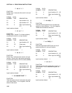
*** 102 SDM-SW8A ***
FUNCTION
The 8 channel SDM-SW8A Switch Closure
Input Module is a peripheral for measuring up
to 8 channels of switch closure or voltage pulse
inputs. Each channel may be configured to
read single-pole double-throw (SPDT) switch
closure, single-pole single-throw (SPST) switch
closure, or voltage pulse. Output options
include counts, duty cycle, or state.
The SW8A is addressed by the datalogger,
allowing multiple SW8A's to be connected to
one datalogger. 16 addresses are available,
but for most applications Campbell Scientific
recommends no more than 4 SW8A's be
connected to one datalogger.