


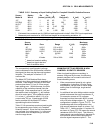

SECTION 13. CR10 MEASUREMENTS
13-17
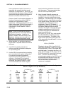
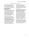
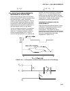
FIGURE 13.4-2. Diagram of Junction Box
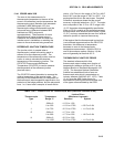
Radiation shielding must be provided when a
junction box is installed in the field. Care must
also be taken that a thermal gradient is not
induced by conduction through the incoming
wires. The CR10 can be used to measure the
temperature gradients within the junction box.
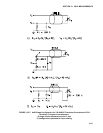
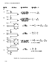
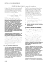
13.5 BRIDGE RESISTANCE
MEASUREMENTS
There are 6 bridge measurement instructions
included in the standard CR10 software. Figure
13.5-1 shows the circuits that would typically be
measured with these instructions. In the
diagrams, the resistors labeled R
s
would
normally be the sensors and those labeled R
f
would normally be fixed resistors. Circuits
other than those diagrammed could be
measured, provided the excitation and type of
measurements were appropriate.
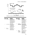
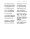
With the exception of Instructions 4 and 8,
which apply an excitation voltage then wait a
specified time before making a measurement,
all of the bridge measurements make one set of
measurements with the excitation as
programmed and another set of measurements
with the excitation polarity reversed. The error
in the two measurements due to thermal emfs
can then be accounted for in the processing of
the measurement instruction. The excitation is
switched on 450 µs before the integration
portion of the measurement starts and is
grounded as soon as the integration is
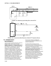
completed. Figure 13.5-2 shows the excitation
and measurement sequence for Instruction 6, a
4 wire full bridge. Excitation is applied
separately for each phase of a bridge
measurement. For example, in Instruction 6, as
shown in Figure 13.5-2, excitation is switched
on for the 4 integration periods and switched off
between integrations.
Instruction 8 measurement sequence consists
of applying a single excitation voltage, delaying
a specified time, and making a differential
voltage measurement. If a delay of 0 is
specified, the inputs for the differential
measurement are not switched for a second
integration as is normally the case (Section
13.2). The result stored is the voltage
measured. Instruction 8 does not have as good
resolution or common mode rejection as the
ratiometric bridge measurement instructions. It
does provide a very rapid means of making
bridge measurements as well as supplying
excitation to circuitry requiring differential
measurements. This instruction does not
reverse excitation. A 1 before the excitation
channel number (1X) causes the channel to be
incremented with each repetition.
The output of Instruction 8 is simply the voltage
measurement. When 8 is used to measure a
full bridge (same connections as Instruction 6 in
Figure 13.5-1), the result is V
1
which equals V
x
(R
3
/(R
3
+R
4
) - R
2
/(R
1
+R
2
)). (In other words, to
make the output the same as Instruction 6, use
a factor of 1000/V
x
in the multiplier.)