


13-1
SECTION 13. CR10 MEASUREMENTS
13.1 FAST AND SLOW MEASUREMENT
SEQUENCE
The CR10 makes voltage measurements by
integrating the input signal for a fixed time and
then holding the integrated value for the analog
to digital (A/D) conversion. The A/D conversion
is made with a 13 bit successive approximation
technique which resolves the signal voltage to
approximately one part in 7500 of the full scale
range on a differential measurement (e.g.,
1/7500 x 2.5 V = 333 uV). The resolution of a
single-ended measurement is one part in 3750.
Integrating the signal removes noise that could
create an error if the signal were instantaneously
sampled and held for the A/D conversion. There
are two integration times which can be specified
for voltage measurement instructions, the slow
integration (2.72 ms), or the fast integration (250
us). The slow integration time provides a more
noise-free reading than the fast integration time.
Integration time is specified in the Range Code
of the measurement instruction. Instructions 1 -
14 RANGE codes:
Slow (2.72 ms Integration time)
Fast (250 us Integration time)
60 Hz rejection
50 Hz rejection
Full Scale range
1112131± 2.5 mV
2122232± 7.5 mV
3132333± 25 mV
4142434± 250 mV
5152535± 2500 mV
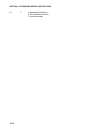
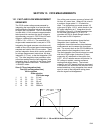
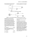
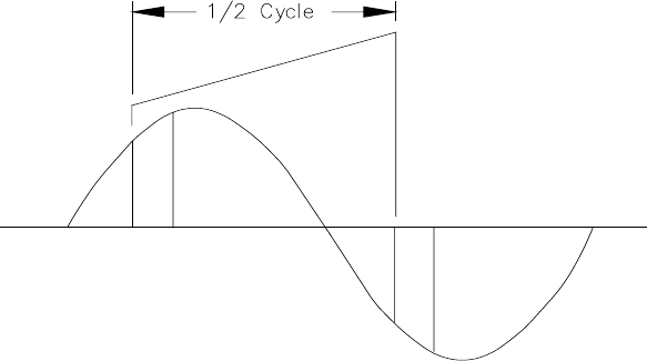
One of the most common sources of noise is 60
Hz from AC power lines. Where 60 Hz noise is
a problem, range codes 21 - 25 should be
used. Two integrations are made spaced 1/2
cycle apart (Figure 13.2-2), which results in the
AC noise integrating to 0. Integration time for
the 2500 mV range is 1/10 the integration time
for the other gain ranges (2.72 ms). For
countries with 50 Hz power Range codes 31 -
35 are used for 50 Hz rejection.
There are several situations where the fast
integration time is preferred. The fast
integration time minimizes time skew between
measurements and increases the throughput
rate. The current drain on the CR10 batteries is
lower when the fast integration time is used.
The fast integration time should always be used
with the AC half bridge (Instruction 5) when
measuring AC resistance or the output of an
LVDT. An AC resistive sensor will polarize if a
DC voltage is applied, causing erroneous
readings and sensor decay. The induced
voltage in an LVDT decays with time as current
in the primary coil shifts from the inductor to the
series resistance; a long integration time would
result in most of the integration taking place
after the signal had disappeared.
FIGURE 13.1-1. 50 and 60 Hz Noise Rejection