


SECTION 13. CR10 MEASUREMENTS
13-2
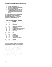
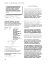
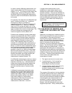
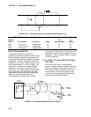
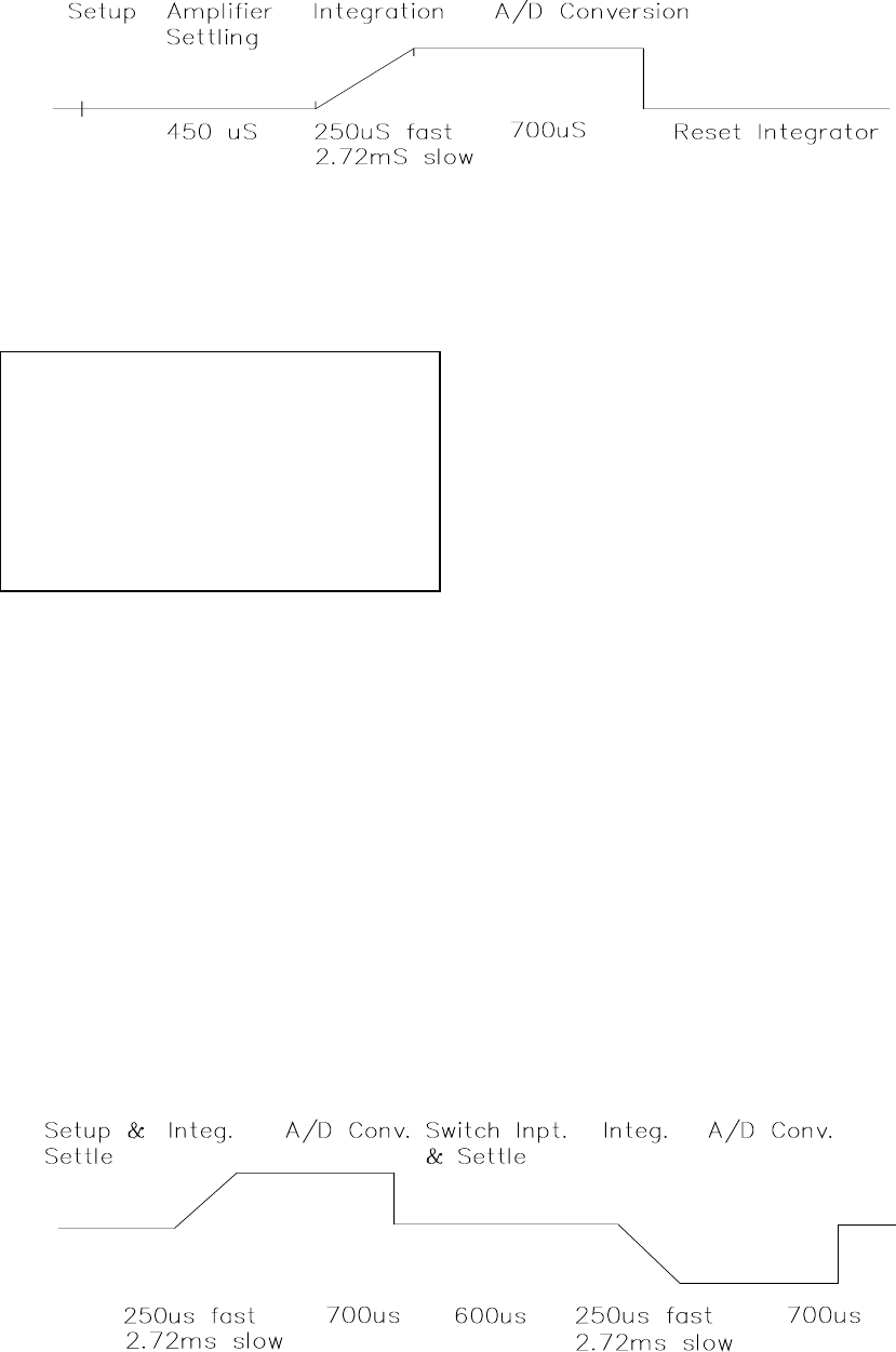
FIGURE 13.2-1. Timing of Single-Ended Measurement
13.2 SINGLE-ENDED AND
DIFFERENTIAL VOLTAGE
MEASUREMENTS
NOTE: The channel numbering on the old
silver CR10 wiring panel refers to
differential channels. Either the high or low
side of a differential channel can be used
for single-ended measurements. Each side
must be counted when numbering single-
ended channels; e.g., the high and low
sides of differential channel 4 are single-
ended channels 7 and 8, respectively.
The timing and sequence of a single-ended
measurement is shown in Figure 13.2-1. A
single-ended measurement is made on a single
input which is referenced to ground. A single
integration is performed for each measurement.
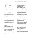
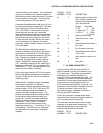
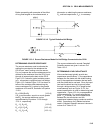
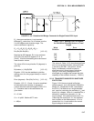
A differential measurement measures the
difference in voltage between two inputs. The
measurement sequence on a differential
measurement involves two integrations. First
with the high input referenced to the low, then
with the inputs reversed (Figure 13.2-2).
The CR10 computes the differential voltage by
averaging the magnitude of the results from the
two integrations and using the polarity from the
first. An exception to this is the differential
measurement in Instruction 8 which makes only
one integration.
Because a single-ended measurement is
referenced to CR10 ground, any difference in
ground potential between the sensor and the
CR10 will result in an error in the measurement.
For example, if the measuring junction of a
copper-constantan thermocouple, used to
measure soil temperature, is not insulated and
the potential of earth ground is 1 mV greater at
the sensor than at the point where the CR10 is
grounded, the measured voltage would be 1
mV greater than the thermocouple output or
approximately 25°C high.
Another instance where a ground potential
difference creates a problem is in a case such
as described in Section 7.2, where external
signal conditioning circuitry is powered from the
same source as the CR10. Despite being tied
to the same ground, differences in current drain
and lead resistance result in different ground
potential at the two instruments. For this
reason a differential measurement should be
made on an analog output from the external
signal conditioner. Differential measurements
MUST be used where the inputs are known to
be different from ground, such as is the case
with the output from a full bridge.
FIGURE 13.2-2. Differential Voltage Measurement Sequence