


SECTION 14. INSTALLATION AND MAINTENANCE
14-7
14.4 SOLAR PANELS
Auxiliary photovoltaic power sources may be
used to maintain charge on lead acid batteries.
When selecting a solar panel, a rule-of-thumb is
that on a stormy overcast day the panel should
provide enough charge to meet the system
current drain (assume 10% of average annual
global radiation, kW/m
2
). Specific site
information, if available, could strongly
influence the solar panel selection. For
example, local effects such as mountain
shadows, fog from valley inversion, snow, ice,
leaves, birds, etc. shading the panel should be
considered.
Guidelines are available from the Solarex
Corporation for solar panel selection called
"DESIGN AIDS FOR SMALL PV POWER
SYSTEMS". It provides a method for
calculating solar panel size based on general
site location and system power requirements.
If you need help in determining your system
power requirements contact Campbell
Scientific's Marketing Department.
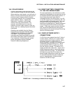
14.5 DIRECT BATTERY CONNECTION
TO THE CR10 WIRING PANEL
For some applications, size restrictions or other
operational considerations may preclude the use
of Campbell Scientific power supply options. In
these cases the power supply may be
connected directly to the wiring panel. Any 9.6
to 18 VDC supply may be connected to the 12 V
and G terminals on the wiring panel. The metal
surfaces of the wiring panel and mounting
bracket are at power ground. Make connections
to the wiring panel first and then to the power
supply. If the power supply must be connected
first, connect the positive to the wiring panel
before the ground to avoid shorting to the wiring
panel or mounting bracket.
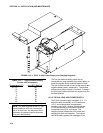
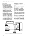
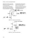
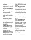
14.6 VEHICLE POWER SUPPLY
CONNECTIONS
If a CR10 is to be powered from the 12 Volts of
a motor vehicle, a second 12 V supply is also
required at the time of vehicle start-up. When
the starting motor of a vehicle with a 12 V
electrical system is engaged, the voltage drops
considerably below the nominal 12 V, which
would cause the CR10 to malfunction every
time the vehicle is started. The second 12 V
supply prevents this malfunction. Figure 14.6-1
shows the general case for connecting the two
supplies to the Wiring Panel. The diode allows
the vehicle to power the CR10 without the
second supply attempting to power the vehicle.
To reduce the potential for ground reference
errors in measurements, the ground lead
should be 16 AWG or larger.
FIGURE 14.6-1. Connecting to Vehicle Power Supply