CHAPTER 13: Adding and Replacing Components www.emachines.com
160
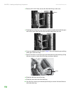
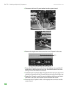
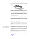
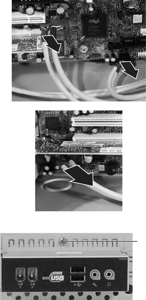
5 Disconnect the front I/O panel cables from the system board.
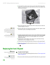
6 Remove the single screw that secures the front I/O panel to the case.
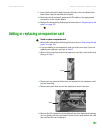
7 Rotate the I/O panel down until it faces the tabletop, then pull the I/O
panel and its cables away from the case. Note the location of the hole
through which the cables are threaded.
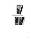
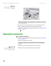
8 Thread the new I/O panel’s cables through the hole in the case, then insert
the tabs in the bottom of the I/O panel into the slots in the front of the case.
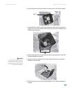
9 Rotate the I/O panel up until its screw hole aligns with the screw hole in
the front of the case, then secure it to the case with the screw.
10 Reconnect the I/O panel’s cables to the appropriate connectors on the
system board.
Screw


