


Summit Family Switches Hardware Installation Guide
105
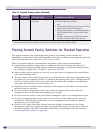
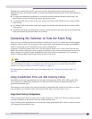
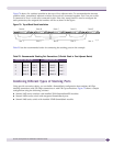
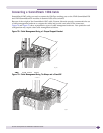
Figure 74 shows five switches installed at the tops of five adjacent racks. To accommodate the shortest
possible cables, immediately adjacent switches are not always connected together. Port 2 on one switch
is connected to Port 1 on the next connected switch. If the easy setup feature is used to configure the
stack parameters, the assigned slot numbers will be as shown in the figure.
Figure 74: Top-of-Rack Stack Installation
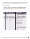
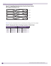
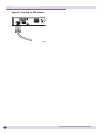
Table 23 lists the recommended order for connecting the stacking ports in this example.
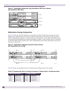
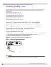
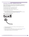
Combining Different Types of Stacking Ports
Using special conversion cables, you can build a SummitStack configuration that combines 40-Gbps
stacking connections with 256-Gbps connections or with 128-Gps connections. Figure 75 shows a sample
configuration using the following switches:
● Summit X650 series switches with installed VIM1-SummitStack256 modules
● Summit X450a series switch with integrated SummitStack ports
● Summit X480 series switch with installed VIM2-SummitStack module
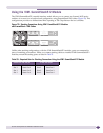
Table 23: Recommended Stacking Port Connections (5-Switch Stack in Five Adjacent Racks)
Connect this slot and port . . . . . . To this slot and port
1 Rack A Port 2 Slot 2 Rack B Port 1
2 Rack B Port 2 Slot 3 Rack D Port 1
3 Rack D Port 2 Slot 4 Reck E Port 1
4 Rack E Port 2 Slot 5 Rack C Port 1
5 Rack C Port 2 Slot 1 (Rack A Port 1
SH_173
Rack A
Rack B
Rack D
Rack E
Rack C
Slot 1 Slot 2
Slot 3
Slot 4
Slot 5