


Technical Specifications
Summit Family Switches Hardware Installation Guide
266
Console Connector Pinouts
This section provides connector pinouts for the console port and associated cables.
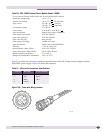
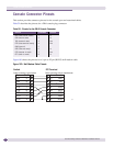
Table 52 describes the pinouts for a DB-9 console plug connector.
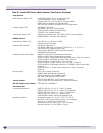
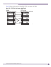
Figure 183 shows the pinouts for a 9-pin to 25-pin (RS-232) null-modem cable.
Figure 183: Null-Modem Cable Pinouts
Table 52: Pinouts for the DB-9 Console Connector
Function Pin Number Direction
DCD (data carrier detect) 1 In
RXD (receive data) 2 In
TXD (transmit data) 3 Out
DTR (data terminal ready) 4 Out
GND (ground) 5 -
DSR (data set ready) 6 In
RTS (request to send) 7 Out
CTS (clear to send) 8 In
Screen
TxD
RxD
Ground
RTS
CTS
DSR
DCD
DTR
Cable connector: 9-pin female
Switch
Cable connector: 25-pin male/female
25pin
PC/Terminal
Screen
RxD
TxD
Ground
RTS
DTR
CTS
DSR
DCD
Shell
3
2
5
7
8
6
1
4
1
3
2
7
4
20
5
6
8