


Summit Family Switches Hardware Installation Guide
61
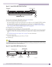
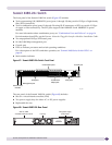
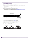
Summit X480-24x Switch
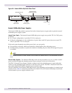
The front panel of the Summit X480-24x switch (Figure 47) includes:
● Twelve autosensing 100/1000BASE-X ports (ports 1 through 12) that provide 12 Gbps of high-density
fiber (SFP) connectivity
● Twelve combination ports (ports 13 through 24) using RJ-45 connectors or SFPs to provide 12 Gbps
of copper or fiber connectivity. The SFP ports support both 100BASE-X and 1000BASE-X optical
modules.
For more information about combination ports, see “Combination Ports and Failover” on page 16.
For information about SFPs, see the Extre me Ne two rks Plugg a ble Inte rfa c e Mo dule s Ins ta lla tio n G uide .
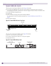
● Two unpopulated 10-Gbps XFP-based ports
● 10/100/1000 Mbps management port
● Console port
● LEDs to indicate port status and switch operating conditions.
For a description of the LEDs and their operation, see “Summit X480 Series Switch LEDs” on
page 66.
● Stack number indicator
Figure 47: Summit X480-24x Switch Front Panel
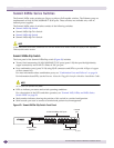
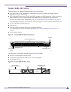
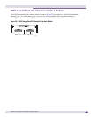
The rear panel of the Summit X480-24x switch (Figure 48) includes:
● Slot for a virtual interface module (VIM)
● Two power supply bays for either AC or DC power supplies
● Replaceable fan tray
Figure 48: Summit X480-24t Rear Panel
Stack number
indicator
XFP ports
Management port
Combination ports
SFP ports
10/100/1000
Mbps ports
Console port
SH_120
Slot for VIM2
versatile interface module
Fan tray
Two power supply
(PSU) slots
SH_154