


Summit Family Switches
Summit Family Switches Hardware Installation Guide
66
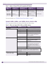
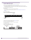
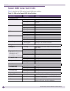
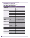
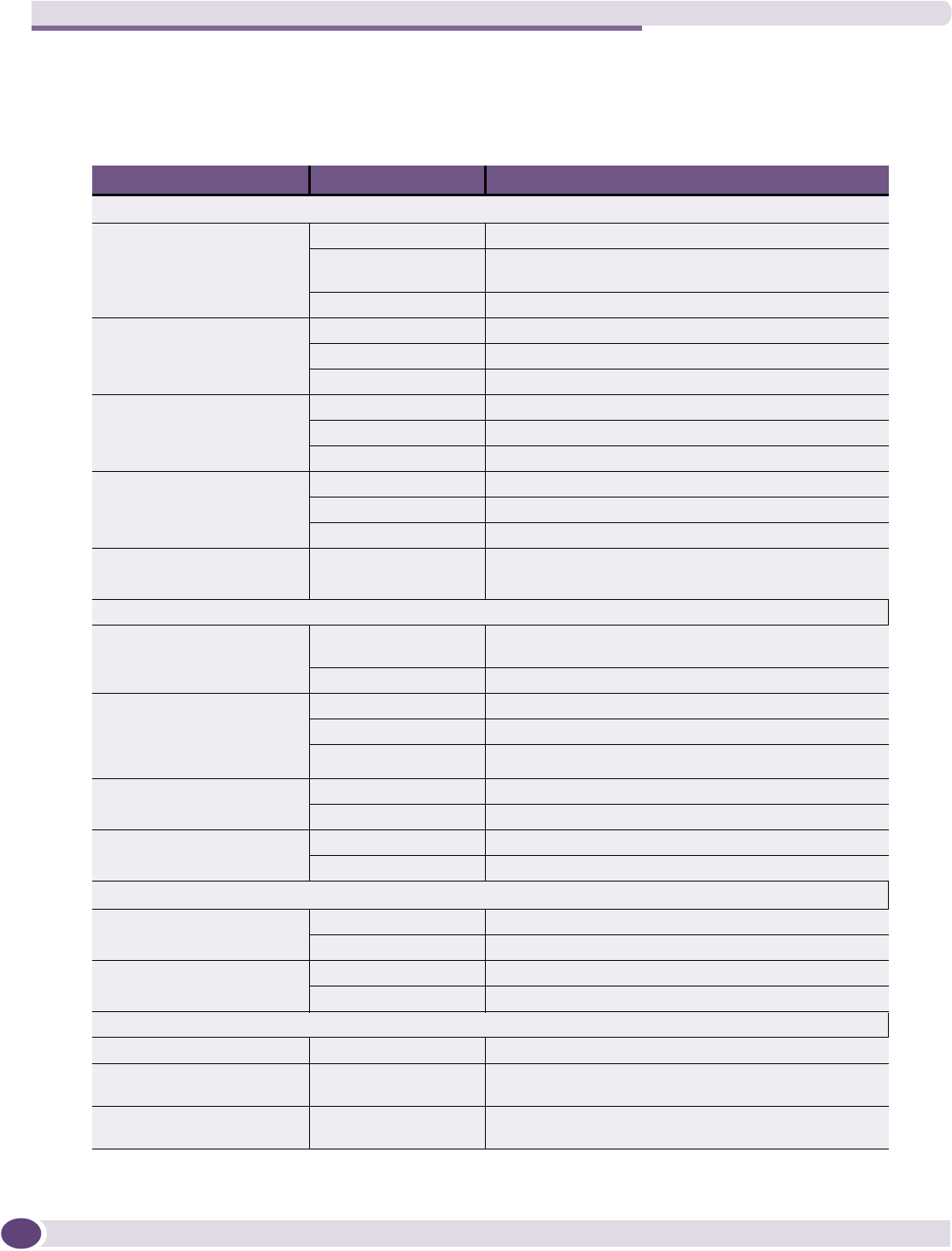
Summit X480 Series Switch LEDs
Table 14 describes the LEDs on the Summit X480 series switches.
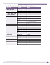
Table 14: LEDs on the Summit X480 Series Switches
Label or Type Color/State Meaning
Front Panel LEDs
MGMT Blinking Green Normal operation
Blinking Amber Power-on self test (POST) failed; diagnostic test in
progress
Off No external power attached
FAN Steady Green Normal operation
Blinking Amber Failure
Off No power
PSU-1 Steady Green Normal operation
Blinking Amber Failure
Off No power
PSU-2 Steady Green Normal operation
Blinking Amber Failure
Off No power
Stack Management 1 – 4 Steady green Link OK on the indicated stack port.
Blinking green Activity on the indicated stack port.
2-digit Stack number Indicator
Left digit (1) Blinking This switch is the stack master node (see description of
right digit).
Off This switch is the stack backup node.
Right digit (1 – 8)
Indicates the position of
this switch in the
SummitStack configuration.
Upper half blinking This switch is the stack master node.
Lower half blinking This switch is the stack backup node.
Lit steadily This switch is a standby node in the stack.
Ethernet Ports
1 – 24 or 1 – 48
Steady Green Link OK
Blinking Green Activity
Management Port Steady Green Link OK
Blinking Green Activity
Back Panel
Stacking Port LED
(on installed VIM)
Steady Green Link OK
Blinking Green Activity
XFP Port LED
(on installed VIM)
Steady Green Link OK
Blinking Green Activity
Power Supply LEDs
Top Steady Green +3.3VSB ok; 12 V ok; PSU is working properly.
Middle Steady Amber Fault condition (for example, 3.3VSB OCP/UCP, 12V
OCP/UCP, or fan failure).
Bottom Steady Green PSU is connected to power. If the cord is connected
and this LED is off, the PSU is defective.