


Summit Family Switches Hardware Installation Guide
189
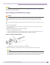
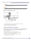
To disconnect and remove an EPS-150DC unit:
1 Attach the ESD strap to your wrist and connect the metal end to the ground receptacle on the top-
right corner of the switch front panel.
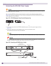
2 De-energize the DC circuit.
3 Remove power from the EPS-150DC power module by unplugging the DC connector from the DC
power supply socket on the rear of the EPS-150DC unit.
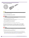
Loosen the retainer nut on the DC power connector and unplug the connector from the back of the
power unit.
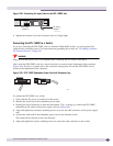
4 At each end of the redundant power cable, unscrew the captive retaining screws on the power
connector and disconnect the cable from the switch and the EPS-150DC unit.
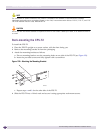
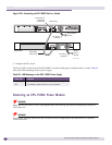
5 Loosen the thumbscrews on the front of the EPS-150DC unit until they are completely free of the
EPS-T tray, and slide the EPS-150 unit out of the tray.
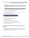
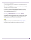
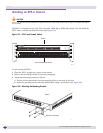
Installing an EPS-600LS External Power Module
You install one, two, or three EPS-600LS power modules (model 10913) in the EPS-C chassis (Model No.
10912) to build an external redundant power system for a Summit PoE-capable switch. A redundant
power cable shipped with the EPS-C chassis provides the connection between the external power
system and the redundant power input connector on the back of the switch.
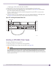
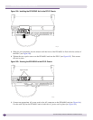
NOTE
An AC power cord is not provided with the EPS-600LS power module. See “Selecting Power Supply Cords” on
page 218 for information about selecting a power cord.
Each EPS-C chassis is shipped with a special redundant power supply cord for connection to the Summit switch.
Make sure that the EPS-C chassis is installed in the rack system before installing an EPS-600LS unit.