


Summit Family Switches Hardware Installation Guide
123
NOTE
For centralized DC power connection, these products are intended to be installed in Restricted Access Locations
(Dedicated Equipment Rooms, Equipment Closets, or the like) in accordance with Articles 110-16, 110-17, and
110-18 of the National Electric Code, ANSI/NFPA 70.
NOTE
An optional redundant power supply, the EPS-150DC, is available for use with the Summit DC-powered switches.
When the EPS-150DC is used with a DC-powered Summit switch, the power supplies (internal and redundant) are
fully fault tolerant and load-sharing. If one power supply fails, the other power supply will provide sufficient power to
operate the switch. Refer to “EPS-150DC External Power Module (with EPS-T2)” on page 76 for further details.
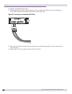
Connecting the Internal DC Power Supply to the DC Source Voltage
Before you connect the switch to a power source, complete the physical installation of the switch in the
equipment rack, as described in “Rack-Mounting a Summit Switch (Models Other than Summit X480
and X650 Series)” on page 120.
If you are installing a Summit DC-powered switch, you must ground the chassis before connecting the
switch to the DC source voltage (see “Grounding a Summit DC-Powered Switch” below).
Grounding a Summit DC-Powered Switch
Before you connect the power input cable to a Summit DC-powered switch, you must ground the
chassis, following the instructions in this section.
Gather the following materials to ground the Summit DC-powered switch:
● Stranded copper wire cable, minimum size 14 AWG, maximum size 6 AWG
The wire should be long enough to reach from the installed switch to the facility ground point
● Torque screwdriver with 1/4-inch flat blade
● Additional grounding hardware appropriate to the earth ground connection at your site
WARNING!
Be sure to connect the chassis ground wire before you connect any power cables.
To ground the switch:
1 At one end of the wire, strip the insulation to expose 1/2 inch (12 mm) of bare wire.
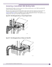
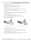
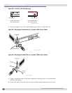
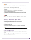
2 Identify the grounding lug on the back of the switch. The grounding lug is next to the edge of the
back panel, identified by the international symbol for earth ground. Depending on the switch model,
the grounding lug may be on either side (see Figure 92).