


Summit Family Switches
Summit Family Switches Hardware Installation Guide
26
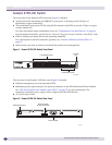
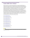
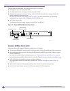
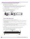
The rear panel of the Summit X250e-24p switch (Figure 12) includes:
● Management port with associated LEDs
● Two high-performance stacking ports with associated LEDs
● Redundant power input connector for use with the EPS-500 External Power Supply (Model No.
10911) with full PoE power support.
See “EPS-500 External Power Supply Unit” on page 76 for more information. The connecting
redundant power supply cable is shipped with the EPS-500 unit.
● AC power input socket.
The internal AC power supply operates from 100 VAC to 240 VAC.
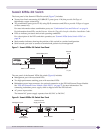
Figure 12: Summit X250e-24p Switch Rear Panel
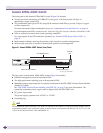
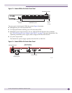
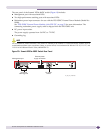
Summit X250e-24x Switch
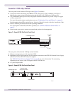
The front panel of the Summit X250e-24x switch (Figure 7) includes:
● Twenty-four 100BASE-FX ports (ports 1–24) that provide 2.4 Gbps of high-density fiber connectivity
● Two combination ports (ports 25–26) using RJ-45 connectors and SFPs to provide 2 Gbps of copper
or fiber connectivity
For more information about combination ports, see “Combination Ports and Failover” on page 16.
For information about SFPs, see the Extre me Ne two rks Plugg a ble Inte rfa c e Mo dule s Ins ta lla tio n G uide .
● LEDs to indicate port status and switch operating conditions.
For a description of the LEDs and their operation, see “Summit X250e Series Switch LEDs” on
page 34.
● Stack number indicator showing the position of this switch in a stacked configuration.
● Serial console port used to connect a terminal and perform local management.
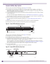
10 Gigabit
stacking ports
Management port
Power socket
External power
supply connection
SH_041