


Summit Family Switches
Summit Family Switches Hardware Installation Guide
48
NOTE
For centralized DC power connection, this product is intended to be installed in a restricted access location (such as
a dedicated equipment room, equipment closet, or central office) in accordance with Articles 110-16, 110-17, and
110-18 of the National Electric Code, ANSI/NFPA 70.
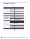
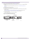
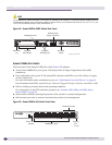
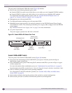
Figure 34: Summit X450a-24tDC Switch Rear Panel
Summit X450a-24x Switch
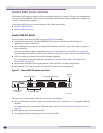
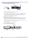
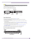
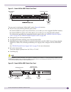
The front panel of the Summit X450a-24x switch (Figure 35) includes:
● Twenty fixed 1000BASE-X ports (ports 1-20) that provide 20 Gbps of high-density fiber (SFP)
connectivity
● Four combination ports (ports 21-24) using RJ-45 connectors and SFPs to provide 4 Gbps of copper
or fiber connectivity
For more information about combination ports, see “Combination Ports and Failover” on page 16.
For information about SFPs, see the Extre me Ne two rks Plugg a ble Inte rfa c e Mo dule s Ins ta lla tio n G uide .
● LEDs to indicate port status and switch operating conditions.
For a description of the LEDs and their operation, see “Summit X450, X450a, and X450e Series
Switch LEDs” on page 58.
● Stack number indicator showing the position of this switch in a stacked configuration.
● Serial console port used to connect a terminal and perform local management.
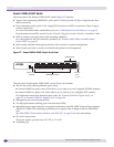
Figure 35: Summit X450a-24x Switch Front Panel
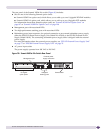
-48 V
2.0 A Max
10 Gigabit
uplink option
Management port
10 Gigabit
stacking ports
DC power
socket
External power
supply connection
Grounding
lug
SH_026_rear_X450a-24tdc
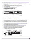
STACK NO.
Solid ON = Link
Blinking = Activity
10G
MGMT
FAN
PSU-1
PSU-E
1
2
Stack
1
2
2
1
4
3
6
5
8
7
10
9
12
11
14
13
16
15
18
17
20
19
22
21
24
23
22X
21X
24X
23X
SH_033B
1000BASE-X ports
Combination ports
Console
port
Stack number
indicator