


Summit Family Switches
Summit Family Switches Hardware Installation Guide
58
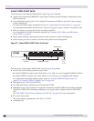
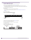
For more information, see “EPS-600LS External Power Module” on page 77.
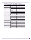
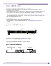
Summit X450, X450a, and X450e Series Switch LEDs
Table 12 describes the LEDs for the Summit X450, X450a, and X450e switches.
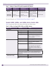
Table 11: Number of External PSUs and Corresponding PoE Behavior
Internal PSU
Status
EPS-600LS (1x) EPS-600LS (2x) EPS-600LS (3x)
External PSU/Chassis
Failed/Disconnected
Internal PSU:
Power On
370 W of
redundant power
740 W of
external power only
Internal PSU disabled
740 W of
external power only
with 2:1 redundancy
Internal PSU disabled
370 W of
internal power only
Internal PSU:
Power Failure
370 W of
external power only
740 W of
external power only
740 W of
external power only
with 2:1 redundancy
No PoE power
Table 12: LEDs on the Summit X450, X450a, and X450e Switches
Label or Type Color/State Meaning
Front Panel
MGMT Blinking green (fast) Power-on self-test (POST) in progress.
Steady green POST passed. System is booting image.
Blinking green (slow) Normal operation
Blinking amber Switch diagnostics running.
or
System is disabled. POST failed or
system overheated.
Off No external power attached
FAN Steady green Normal operation
Steady amber* A single fan in the array has failed. The
switch can continue to operate
indefinitely.*
Blinking amber Failure
or
Two or more fans in the array have
failed. Because system cooling is
compromised, you should replace the
switch.*
Off No power
* These states for the Fan LED occur only on Summit X450a-48tDC
switches with a manufacturing part number of 800294-00 and
X450a-48tDC-TAA switches with a manufacturing part number of
800337-00.
PSU-I
(Internal power supply)
Steady green Normal operation
Blinking amber Failure
Off No power