Setting up the Elite XL 1-23
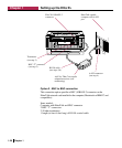
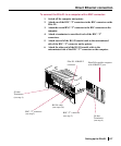
4. Switch on the printer and the printer.
5. Switch on the PC
6. Set the printer for Serial communication.
The 8-pin serial submenu, accessed from printer’s front panel, should
be set to RS422. LocalTalk is the factory default, so you will need to
change the setting. See page 2-4 for instructions on using the front
panel menu system and page 2-10 for information about the 8-pin
serial submenu.
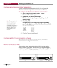
7. Configure the serial interface settings.
In order for successful serial communications between the printer and
the PC to take place, the configuration of the serial interface of each
device must match. See page 2-10 for more information about config-
uring the serial interface.
Note: In order to send PostScript jobs that use Binary Communications Protocol to the Elite
XL RS-422 port, the port must set to PostScript only. If it is set to Auto switch, the
PostScript Binary Communications Protocol will be interpreted as PCL and your document
will not print properly. (See page 2-7 for information on configuring the port.)
Ethernet network connection
Elite XL’s that include an Ethernet network interface card can print over
Ethernet networks that use the EtherTalk network protocol. EtherTalk is Apple’s
name for the AppleTalk network protocol running over Ethernet cabling. (Note:
The Elite XL Ethernet network interface is available as a user-installable option
for models that do not come with it standard. See page I-1.)
The Ethernet cabling system provides faster and more reliable communications
than the LocalTalk cabling system. The XL Ethernet interface has connectors
for two types of Ethernet cables: 10BASE-T and 10BASE-2.
The following sections provide information about the different methods for
connecting the Elite XL to your Ethernet network.
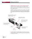
10BASE-T (Unshielded Twisted-Pair or UTP) network connection
The Elite XL connects to 10BASE-T Ethernet via the 10BASE-T (RJ-45)
connector on the network card. The cabling used is Unshielded Twisted-Pair
(UTP). A UTP cable consists of four individually twisted pairs of insulated
wire that are surrounded by only the outside shell of the cable. Nodes (comput-
ers, printers, etc.) on a network using UTP cabling must be connected to a hub
in a star topology. Multiple hubs may be connected to each other linearly (using
an RG-58 coax backbone) or hierarchically with additional UTP cables,
depending on the type of hub.
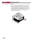
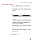
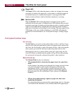
Interface connections for the Elite XL
Note: Please refer to
your Ethernet hub
documentation for
more information about
setting up the network.


