


INSTALLING THE M208 ON THE NETWORK: Connecting the M208 to the Network 17
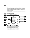
Connecting the M208 to the Network
To connect the M208 to the network:
1 Connect Data Terminal Equipment (DTE) and other hubs/backbone to the appro-
priate ports (10Base-T or AUI port). Please see Hub Installation on page 20 for
further details.
1 Connect peripherals to the appropriate I/O ports. Please see Connecting Peripher-
als on page 17 for details on each of the M208’s I/O ports.
2 Unpack and plug in the power supply. The connector plugs into the back of the
M208. Watch the lights on the from panel of the M208 as they cycle through the
power-on self test. When the test is complete, the POWER light is on and STAT is
flashing.
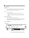
Connecting Peripherals
A maximum of three devices can be attached to an M208’s I/O ports at the same time;
one on the parallel port and two on the serial ports.
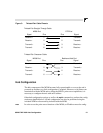
Parallel Port Connections (PRN)
One 25-pin female DB-25S connector with an IBM PC compatible pinout are pro-
vided on the rear panel for connection to a printer using a parallel port. This port can
be configured with various parameters depending on the attached printer. These
parameters include:
• ackmode for printers (usually non-laser printers) that use the
ACK signal for the
trigger of next data transfer rather than the BUSY signal,
• autofeed for printers (usually non-laser printers) that require the
AUTOFD line to
be asserted,
• bbmode for simulating an attached printer,
• fastmode for high performance parallel interfaces that can handle an increased
transfer rate,
• slowmode for slower parallel interfaces which require slower transfer rates.
•vslowmode for printers that require ever slower data transfer rates.