


4 - 20
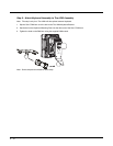
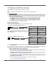
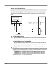
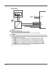
Ignition Control Wiring Diagram
Ignition wire must be connected and either of the Ignition Control power modes must be selected from the
Power Schemes tab of the Power Options (page 5-22) control panel. When switched vehicle power is avail-
able the Thor VM2 ignition signal wire can be connected (less than 1mA over input voltage range) to the
switched circuit to allow the Thor VM2 to power on when the vehicle is switched on. When the vehicle is
switched off, more aggressive power management settings are enabled to preserve the vehicle battery
charge.
.
CAUTION
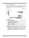
For battery powered vehicles:
• Red wire is connected to battery positive. If there is a red wire and a red/white wire, twist them
together and connect to battery positive.
• Black wire must be connected to battery negative. If there is a black wire and a black/white wire,
twist them together and connect to battery negative.
• Green wire must be connected to the vehicle chassis ground.
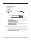
For internal combustion engine powered vehicles:
• Red wire is connected to battery positive. If there is a red wire and a red/white wire, twist them
together and connect to battery positive.
• Black wire must be connected to battery negative. If there is a black wire and a black/white wire,
twist them together and connect to battery negative.
• Green wire is connected to the vehicle chassis ground, which can also be battery negative.
WARNING
For proper and safe installation, the input power cable must be connected to a fused circuit on the ve-
hicle. If the supply connection is made directly to the battery, the fuse should be installed in the positive
lead within 5 inches of the battery’s positive (+) terminal. The fused circuit requires a maximum time
delay (slow blow) fuse with a current rating as noted below.
•For 12VDC input, use a 10A slow blow fuse that has a DC voltage rating greater than 12VDC.
•For 24VDC input, use a 6A slow blow fuse that has a DC voltage rating greater than 24VDC.
•For 36VDC input, use a 4A slow blow fuse that has a DC voltage rating greater than 36VDC.
•For 48VDC input, use a 3A slow blow fuse that has a DC voltage rating greater than 48VDC.
Note: For North America, a UL Listed fuse is to be used.
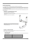
Existing Circuitry On Vehicle
Battery
Main Switch
-Vo
+Vo
Fuse - See
Warning
statement below
Ignition
See Caution statement below
Quick Mount
Smart Dock
Circular
Power
Connector
COM1 or COM2
Connector
Cable for optional
screen blanking
connection
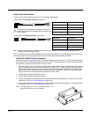
Red
Black
Green
Blue
Red/White (if present)
Black/White (if present)
!
!