


4 - 34
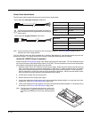
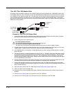
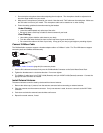
User-Supplied Cable
A user-supplied cable can be used as well. Pins 7 and 8 must be connected as detailed below. No other pins
are to be connected.
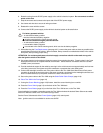
The user-supplied cable is installed as follows:
1. Connect the wire from Pin 8 of the cable to the switched side of the Screen Blanking Box or to a user-sup-
plied switch.
2. Connect the wire from Pin 7 of the cable to the unswitched side of the Screen Blanking Box or to a user-
supplied switch.
3. Connect the D9 serial connector to either COM1 or COM2 serial port on the Thor VM2 Quick Mount
Smart Dock.
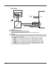
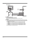
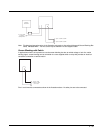
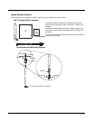
Screen Blanking Box
It is assumed that the motion sensing circuitry in the illustrations below is powered by internal vehicle circuitry.
Please refer to the appropriate illustration below for Screen Blanking Box wiring diagrams.
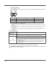
DB9 Female Function with Screen Blanking Box Function with Switch
1 -6, 9 Not Used Not Used
7 (RTS) Connected to Screen Blanking Box, unswitched side Connected to Switch
8 (CTS) Connected to Screen Blanking Box, switched side Connected to Switch
Screen Blanking
Box Terminal
Connection
12-xxV Input from vehicle motion sensing circuitry.
Please refer to label on Screen Blanking Box for allowable voltage input range.
GND DC -
These two terminals are for connecting a serial cable:
• If using an optional Honeywell screen blanking cable, VM1080CABLE, connect the
gray wire to the switched side of the connection and connect the black wire to the
unswitched side.
• If using a user-supplied cable, the cable must be constructed so that Pin 7 (RTS)
connects to switched side of the connection and Pin 8 (CTS) connects to the
unswitched side.
CAUTION - Do not exceed the maximum input voltage, either 60 or 72VDC, specified on the Screen Blanking
Box label when using this configuration.
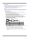
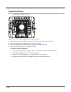
PIN7
PIN 8
PIN 5
PIN1
Unswitched Switched
!