Chapter 7. Installation planning 117
3. Ensure that the floor area provides enough stability to support the weight of the fully
configured DS6000 series and associated components.
4. Ensure that you have adequate rack space for your hardware. Calculate the amount of
space that the storage units will use. Don’t forget to leave enough space for future
upgrades.
5. Ensure that your racks have space for the clearances that the DS6000 series requires for
service and the requirements for floor loading strength.
Floor load requirements
It is very important that your location meets the floor load requirements. This section provides
information you need to ensure that your physical site meets the installation requirements for
the DS6000 series.
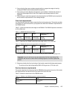
Table 7-1 gives the dimensions and weight of the DS6800. The DS6000 expansion enclosure
is of the same size.
Table 7-1 DS6800 dimensions and weight
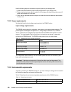
Table 7-2 describes the DS6800 dimensions and weight within a 2101-200 rack.
Table 7-2 DS6800 dimensions and weight within a 2101-200 rack
1. Find out the floor load rating of the location where you plan to install the storage units.
2. Determine whether the floor load rating of the location meets the following requirements:
– The minimum floor load rating used by IBM is 342 kg per sq m (70 lb per sq ft).
Service clearance requirements
This section describes the clearances that the DS6000 series requires for service. We include
the clearances that are required on the front and to the rear of the rack.
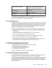
Table 7-3 shows the clearances for the DS6000 series.
Table 7-3 DS6800 or the DS6000 expansion enclosure clearance
Height Width Depth Maximum weight (fully
configured)
5.25 inches
(0.134 meters)
18.80 inches
(0.478 meters)
24.00 inches
(0.610 meters)
109 lbs.
(49.6 kg)
Height Width Depth Maximum weight (fully
configured)
71.00 inches
(1.804 meters)
25.40 inches
(0.644 meters)
43.30 inches
(1.908 meters)
2034 lbs.
(904 kg))
Important: If you do not know or are not certain about the floor load rating of the
installation site, be sure to check with the building engineer or another appropriate
person.
Front Rear
12.00 inches
0.305 m
18.00 inches
0.457 m


