


Chapter 2. Components 31
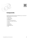
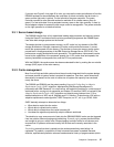
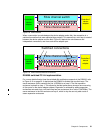
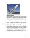
Figure 2-8 Disk enclosure
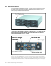
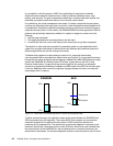
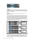
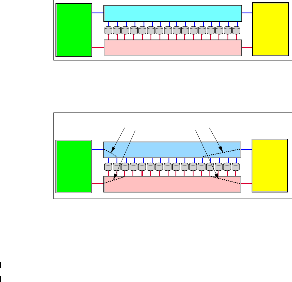
When a connection is made between the device adapter and a disk, the connection is a
switched connection that uses arbitrated loop protocol. This means that a mini-loop is created
between the device adapter and the disk. Figure 2-9 depicts four simultaneous and
independent connections, one from each device adapter port.
Figure 2-9 Disk enclosure switched connections
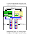
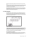
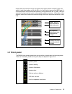
DS6000 switched FC-AL implementation
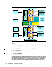
For a more detailed look at how the switched disk architecture expands in the DS6000, refer
to Figure 2-10 on page 32. It depicts how the DS6000 is divided into two disk loops. The
server enclosure (which contains the first 16 DDMs) is on loop 0. The first expansion
enclosure is placed on loop 1. This allows for the best performance since we are now using
all four ports on the device adapter chipset. Expansion is achieved by adding expansion
enclosures onto each loop, until each loop has four enclosures (for a total of 128 DDMs). The
server enclosure is the first enclosure on loop 0, which is why we can only add a total of
seven expansion enclosures.
Controller 0
device
adapter
Fibre channel switch
Controller 1
device
adapter
Fibre channel switch
Controller 0
device
adapter
Fibre channel switch
Controller 1
device
adapter
Switched connections
Fibre channel switch