


Chapter 2. Components 37
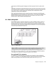
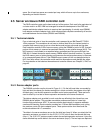
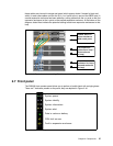
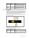
these cables are pictured in orange and green (which appear darker if viewed in black and
white). In each case cables run from the
disk contrl ports to the in ports of the SBOD card. A
second expansion enclosure has been added by running cables from the
out ports on the first
expansion enclosure to the
in ports on the second expansion enclosure. At the bottom of the
diagram, dotted lines indicate the potential cabling to add more expansion enclosures to that
loop
Figure 2-15 Expansion enclosure cabling (Disk Contrl ports on loop 1)
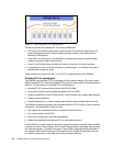
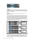
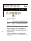
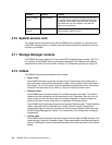
2.7 Front panel
The DS6000 front operator panel allows you to perform a health check with a single glance.
There are 7 indicators present on the panel; they are depicted in Figure 2-16.
Figure 2-16 DS6000 front panel
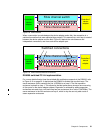
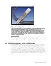
Cables attach to
server enclosure
disk contrl ports
First expansion
enclosure on loop 1
(first enclosure
on loop)
Second expansion
enclosure on loop 1
(second enclosure
on loop)
System information
System alert
Data in cache on battery
System power
System identify
CRU fault on rear
Fault in expansion enclosure