


Chapter 2. Components 25
2.2 Expansion enclosure
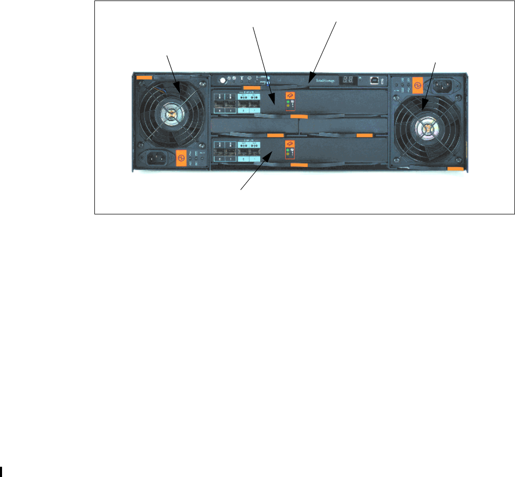
The DS6000 expansion enclosure is used to add capacity to an existing DS6800 server
enclosure. From the front view, it is effectively identical to the server enclosure (so it is not
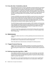
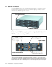
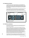
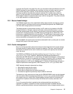
pictured). The rear view is shown in Figure 2-3. You can see the left and right power supplies,
the rear display panel, and the upper and lower SBOD (Switched Bunch Of Disks) controllers.
The power supplies and rear display panel used in the expansion enclosure are identical to
the server enclosure.
The rear view shows two small but important differences. First, the RAID controller cards are
replaced with SBOD controller cards. Second, there are no batteries (since there is no
persistent memory in the expansion enclosure). Instead the expansion enclosure has
blockouts where the battery backup units were, to ensure correct airflow within the enclosure.
Figure 2-3 DS6000 expansion enclosure rear view
2.3 Controller architecture
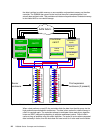
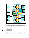
Having described the enclosures themselves, the rest of the chapter explores the technical
details of each of the components. The architecture that connects these components is
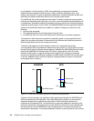
pictured in Figure 2-4 on page 26.
Effectively the DS6800 consists of two controller cards. Each controller card contains an
integrated four port host adapter to connect Fibre Channel and FICON hosts. For the disk
subsystem, each controller card has an integrated four port FC-AL (Fibre Channel Arbitrated
Loop) device adapter that connects the controller card to two separate Fibre Channel loops.
Each switched loop attaches disk enclosures that each contain up to 16 disks. Each
enclosure contains two 22 port Fibre Channel switches. Of these 22 ports, 16 are used to
attach to the 16 disks in the enclosure and four are used to interconnect with other
enclosures. The remaining two are reserved for internal use. Each disk is attached to both
switches. Whenever the device adapter connects to a disk, it uses a switched connection to
transfer data. This means that all data travels via the shortest possible path.
The attached hosts interact with microcode running on a Power PC® chipset to access data
on logical volumes. The microcode manages all read and write requests to the logical
volumes on the disk arrays. For write I/O operations, the controllers use fast-write, whereby
Power supply
Power supply
Upper SBOD controller Rear display panel
Lower SBOD controller