


56 DS6000 Series: Concepts and Architecture
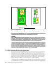
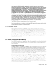
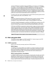
paths) since two paths to the expansion controller would be available for the remaining
controller.
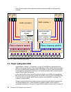
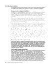
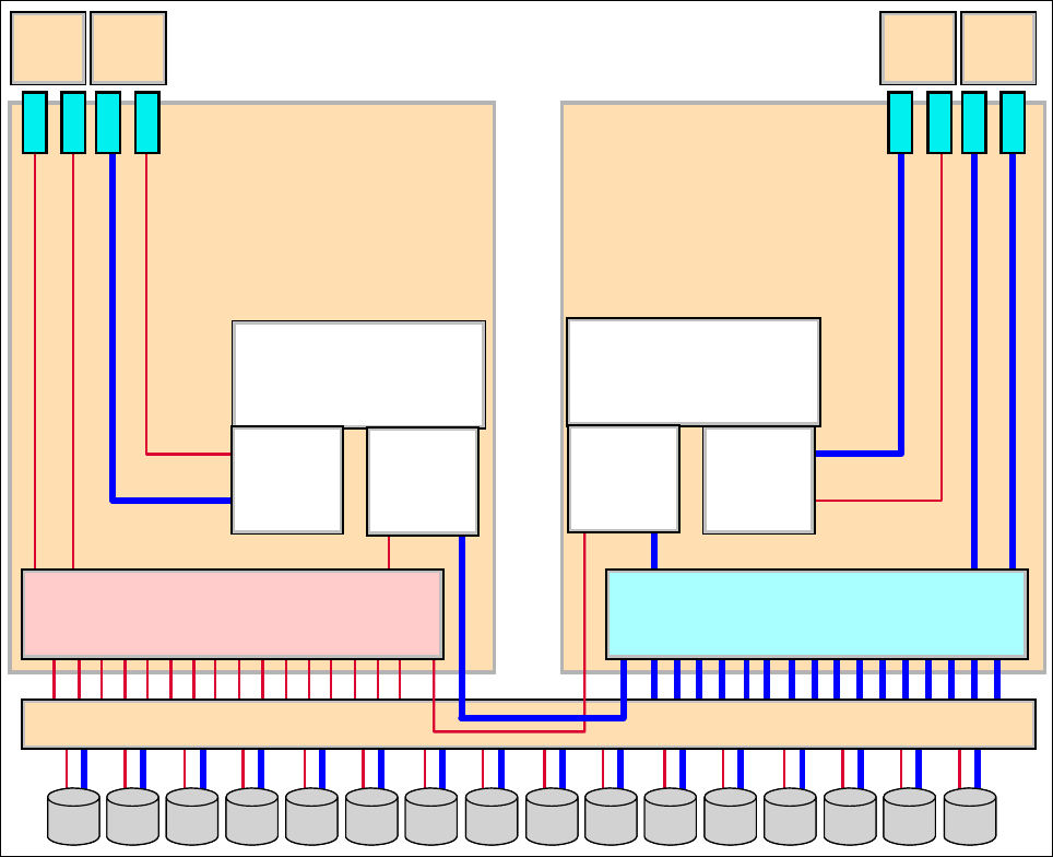
Figure 3-5 DS6000 switched disk connections
3.4 Power subsystem RAS
As discussed in Chapter 2, “Components” on page 23, the DS6000 is equipped with two
BBUs and two power supplies. This provides redundancy in case of either an external power
failure or an internal power subsystem failure. The DS6000 is able to control the state of the
power supplies in the expansion enclosures via in-band commands sent through the device
adapter Fibre Channel connections.
In the event of a BBU failure, the RAID controller that relies on that BBU for data protection
will remove itself from service and go offline until its BBU is fully charged. If both BBUs were
to fail, then the entire system would have to go offline until the problem is corrected. This
possibility is highly unlikely.
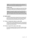
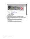
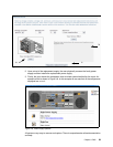
All power components are hot plugable and can usually be replaced without employing the
DS Storage Manager GUI. If more information is needed, however, the GUI could be
employed, as described in “Example 2: Using the GUI to replace a power supply” on page 57.
disk
exp
disk
contrl
disk
contrl
disk
exp
Midplane
RAID controller 0
RAID controller 1
device adapter
chipset
device adapter
chipset
loop 1
engine
loop 1
engine
loop 0
engine
loop 0
engine
Fibre channel switch
Enclosure midplane
Fibre channel switch