


Chapter 3. RAS 47
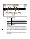
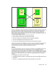
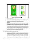
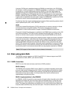
Figure 3-1 DS6800 normal data flow
Figure 3-1 illustrates how the cache memory of controller 0 is used for all logical volumes that
are members of the even LSSs. Likewise, the cache memory of controller 1 supports all
logical volumes that are members of odd LSSs. But for every write that gets placed into
cache, another copy gets placed into the NVS memory located in the opposite controller. So
the normal flow of data for a write is:
1. Data is written to cache memory in the owning controller.
2. Data is written to NVS memory of the alternate controller.
3. The write is reported to the attached host as having been completed.
4. The write is destaged from the cache memory to disk.
5. The write is then discarded from the NVS memory of the alternate controller.
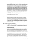
Under normal operation, both DS6800 controllers are actively processing I/O requests. This
section describes the failover and failback procedures that occur between the DS6800
controllers when an abnormal condition has affected one of them.
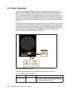
Failover
In the example depicted in Figure 3-2 on page 48, controller 0 in the DS6800 has failed. The
remaining controller has to take over all of its functions. The host adapters located in
controller 0 are now no longer available. All the RAID arrays in the DS6800 will be accessed
from the device adapter in controller 1. First, controller 1 has to process the data it is holding
in NVS. It then starts operating the entire machine in single controller mode. The steps it
takes are:
1. It de-stages the contents of its NVS to disk.
2. The NVS and cache of controller 1 are divided in two, half for the odd LSSs and half for the
even LSSs.
3. Controller 1 now begins processing the writes (and reads) for
all the LSSs.
Cache
memory
for even
LSSs
NVS
for odd
LSSs
NVS
for even
LSSs
Cache
memory
for odd
LSSs
Controller 0 Controller 1