


Chapter 2. Components 35
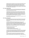
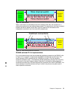
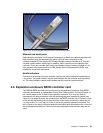
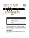
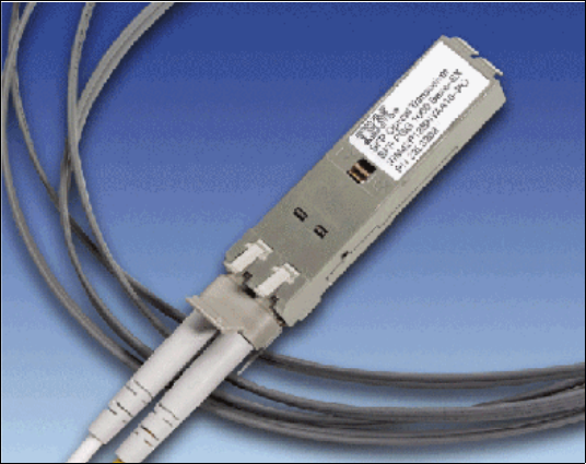
Figure 2-12 SFP hot-plugable fibre port with LC connector fiber cable
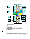
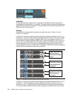
Ethernet and serial ports
Each controller card has a 10/100 copper Ethernet port to attach to a customer-supplied LAN.
Both controllers must be attached to the same LAN and have connectivity to the
customer-supplied PC that has the DS Storage Manager software installed on it. This port
has both a status and an activity light. In addition, there is a serial port provided for each
controller. This is not a modem port and is not intended to have a modem attached to it. Its
main purpose is for maintenance by an IBM System Service Representative (SSR), and
possibly for some initial setup tasks.
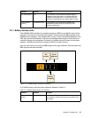
Health indicators
Contained in an orange box, each controller card has two status indicators located below a
chip symbol. The upper indicator is green and indicates that the controller card is powered
on. The lower indicator is amber and indicates that this controller requires service.
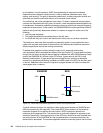
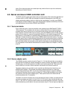
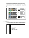
2.6 Expansion enclosure SBOD controller card
The DS6000 SBOD controller card is only found in the expansion enclosure. Each SBOD
controller card contains an independent 22 port Fibre Channel switch. Of these 22 ports, 16
are used to attach to the 16 disks in the expansion enclosure. Four more are used to
interconnect with other enclosures, with the remaining two ports reserved for internal use.
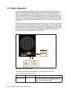
Figure 2-13 on page 36 shows the connectors on the SBOD controller card. The two
in ports
on the left are the switch ports that connect either to the server enclosure (to either the
disk
exp
loop or the disk contrl loop) or to the out ports of a previous expansion enclosure. The
two
out ports on the right (in light blue boxes) are the switch ports that attach to the in ports of
the next expansion enclosure. If there are no extra expansion enclosures then they are not
used.