


Chapter 2. Components 39
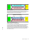
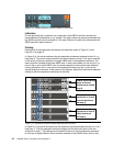
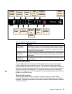
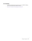
Figure 2-17 DS6000 rear panel
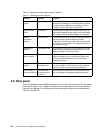
Table 2-2 DS6000 rear panel push buttons
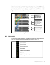
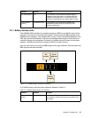
Enclosure ID indicator
The rear display also has an enclosure identifier indicator. This uses two seven-segment
LEDs to display the enclosure identifier number. The left-hand digit displays the device
adapter switched loop the enclosure resides on. This will be 0 or 1 depending on whether the
expansion enclosure is attached to the
disk exp ports or the disk contrl ports respectively. On
the server enclosure it will always be 0. The right-hand digit displays the enclosure base
address. It will range from 0 to 3. This address will be set automatically after the enclosure is
powered on and joins the loop.
Rack identify connector
On the far right-hand end of the rear panel is a connector known as the rack identify
connector. The intention is to allow a user to attach the enclosure to eServer rack identifier
hardware. This allows you to identify in which rack a particular DS6000 storage or expansion
enclosure is located.
Power
control
switch
Data
cache on
battery
System
identify
System
alert
Fault in
external
enclosure
Rack
identify
connector
System
power
System
information
Lightpath
Remind
and
Identify
switches
Fault on
front
CRU
Enclosure
identifier
Button Purpose
Power Control
Switch (white)
This button can be seen on the left-hand side of the rear panel. You press it
once to begin the power on or power off sequence. While the button is present
on the expansion enclosure, only the power button on the server enclosure
can power off the entire complex.
Lightpath
REMIND
Switch (blue)
The upper of the two blue buttons, you push this button to re-activate the light
path remind. This will allow you to identify a failed component that requires
replacement.
Lightpath
IDENTIFY
Switch (blue)
The lower of the two blue buttons, you push this button to activate the system
identify indicator