


34 DS6000 Series: Concepts and Architecture
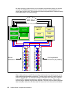
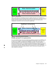
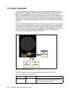
in Figure 2-10 on page 32 (with loop 0 going upwards and loop 1 going in the downwards
direction).
You add one expansion enclosure to each loop until both loops are populated with four
enclosures each (remembering the server enclosure represents the first enclosure on the first
loop). Note that while we use the term disk loops, and the disks themselves are FC-AL disks,
each disk is actually attached to two separate Fibre Channel switches.
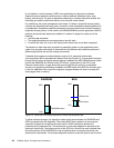
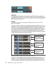
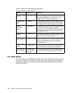
Device adapter port indicators
For each device adapter port, there are two indicators. The top left-hand indicator is green
and is used to indicate port status. The top right-hand indicator is amber and is used to show
port activity.
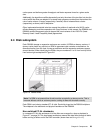
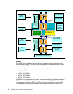
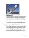
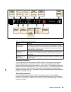
2.5.3 Host adapter ports
From a host connectivity point of view, each DS6800 controller comes with four Fibre
Channel/FICON host ports, giving the machine a total of eight host ports. You can see these
on the right-hand side of Figure 2-11 on page 33. These host ports auto-negotiate to either 2
Gbps or 1 Gbps link speeds. These ports can be either short wave or long wave, which use
multimode or single mode cables respectively, all with LC connectors.
The ports in each controller are effectively on a PCI-X 64 Bit 133 MHz card, the same card
used in the DS8000. The chipset is driven by a new high function/high performance ASIC. To
ensure maximum data integrity it supports metadata creation and checking.
Each port can be either FICON or Fibre Channel Protocol (FCP).The personality of the port is
changeable via the DS Storage Manager GUI. A port cannot be both FICON and FCP
simultaneously, but it can be changed as required.
It is important to understand that an attached host must have connectivity to both controllers.
This is better detailed in Chapter 3, “RAS” on page 45.
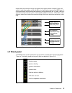
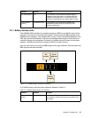
Host adapter port indicators
For each host attachment port, there are three indicators. The top left-hand indicator is green
and is used to indicate port status. The top right-hand indicator is amber and is used to show
a faulty port. The bottom left-hand indicator is green and is used to indicate activity.
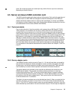
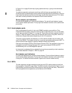
2.5.4 SFPs
The disk expansion and host attachment ports both use SFPs (which stands for small form
factor plugable). These SFPs are 2 Gbps. The RAID controller card pictured in Figure 2-11 on
page 33 does not have these SFPs inserted (which is why you can’t see them). These SFPs
are hot plugable and are supplied as a priced feature of the DS6000.