


36 DS6000 Series: Concepts and Architecture
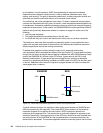
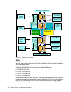
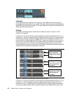
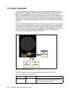
Figure 2-13 DS6000 expansion enclosure SBOD controller card
Indicators
On the right-hand side, contained in an orange box, each SBOD controller card has two
status indicators located below a
chip symbol. The upper indicator is green and indicates that
the SBOD controller card is powered on. The lower indicator is amber and indicates that this
SBOD controller requires service.
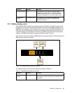
Cabling
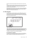
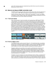
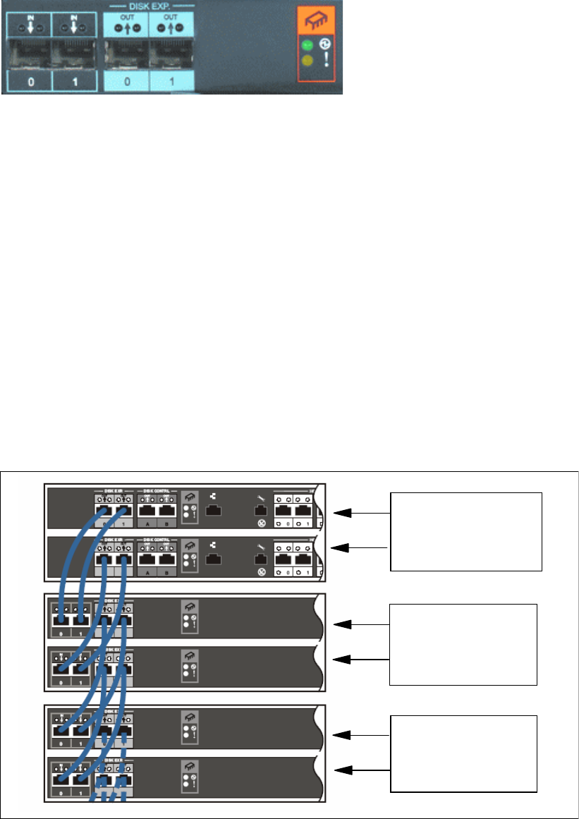
Examples of how the expansion enclosures are cabled are shown in Figure 2-14 and
Figure 2-15 on page 37.
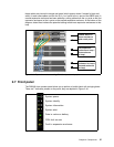
In Figure 2-14, the server enclosure has two expansion enclosures attached to the
disk exp
loop (loop 0). The server enclosure itself is the first enclosure on loop 0. The upper controller
in the server enclosure is cabled to the upper SBOD card in the expansion enclosure. The
lower controller is cabled to the lower SBOD card. In each case cables run from the
disk exp
ports to the
in ports of the SBOD card. A second expansion enclosure has been added by
running cables from the
out ports on the first expansion enclosure to the in ports on the
second expansion enclosure. At the bottom of the diagram, dotted lines indicate the potential
cabling to add more expansion enclosures to that loop.
Figure 2-14 Expansion enclosure cabling (Disk Exp ports on loop 0)
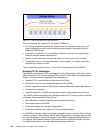
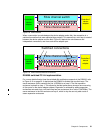
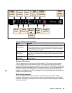
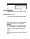
In Figure 2-15, the server enclosure has two expansion enclosures attached to the disk contrl
loop (loop 1). The first expansion enclosure plugged into the disk contrl ports is the first
enclosure on loop 1. The cabling from the server enclosure to the first expansion enclosure
on this loop is slightly different. Each controller attaches to both SBOD cards, which is why
Cables from disk exp
ports on Server
enclosure to extend
loop 0
First expansion
enclosure on loop 0
(second enclosure
on loop 0)
Second expansion
enclosure on loop 0
(third enclosure
on loop 0)