


42 DS6000 Series: Concepts and Architecture
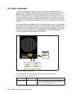
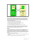
2.10 System service card
The system service card which ships with the DS6800 can be placed in a cavity below the
lower RAID controller card. It is a plastic card that contains important information on how to
maintain your DS6800.
2.11 Storage Manager console
The DS6800 requires a separate PC to act as the DS Storage Manager console. This PC is
not a feature of the DS6800 and must be ordered separately. The hardware and software
requirements for this PC can be found in Chapter 8, “Configuration planning” on page 125.
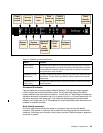
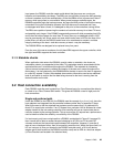
2.12 Cables
The DS6800 ships with three different sorts of cables:
Power cords
Each DS6000 enclosure ships with six power cords. These should allow attachment to
both rack power outlets and standard power outlets. The rack power outlet cords come in
two lengths. The
standard power cords are specified by feature code at time of purchase
(based on the outlet used in your country). Only two of the six cords are used.
Ethernet cables
Each DS6800 server enclosure ships with one Ethernet cross-over cable. This cable is
used during initial configuration of the controllers to set IP addresses. After this, it is not
used. You do not use it to connect the two controllers together for normal operation or
during initial power on (this connectivity is supplied by an Ethernet switch).
Each DS6800 server enclosure ships with two standard Ethernet cables. These should be
used in conjunction with an Ethernet hub or switch (that will need to be supplied or
ordered separately) so that the controllers are able to communicate with each other and
the DS Storage Management Console. This connectivity is for configuration and regular
maintenance.
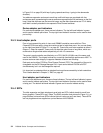
Service cable
Each DS6800 server enclosure ships with a special service cable and DB9 converter. This
cable looks very similar to a telephone cable. These components should be kept aside for
use by an IBM System Service Representative and will normally be used only for problem
debug.
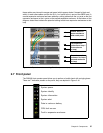
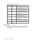
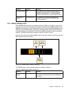
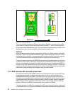
Battery charging
(green)
Battery symbol If this indicator is on solid then the battery backup unit is
fully charged. If this indicator is blinking then the battery
is charging. As the battery approaches full charge the
blink speed will slow. If the indicator is off then the
battery is not operational.
Fault detected
(yellow)
Exclamation mark If this indicator is on solid then a fault has been detected
and this battery requires service.
Indicator Symbol Purpose