


Electrical Specifications
AC Electrical Specifications
Copyright © 2008 Marvell Doc. No. MV-S104859-U0 Rev. E
December 2, 2008, Preliminary Document Classification: Proprietary Information Page 111
8.6.12 Serial Peripheral Interface (SPI) AC Timing
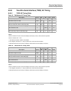
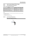
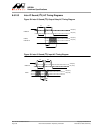
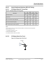
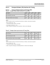
8.6.12.1 SPI (Master Mode) AC Timing Table
Table 60: SPI (Master Mode) AC Timing Table
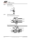
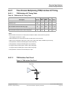
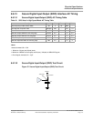
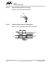
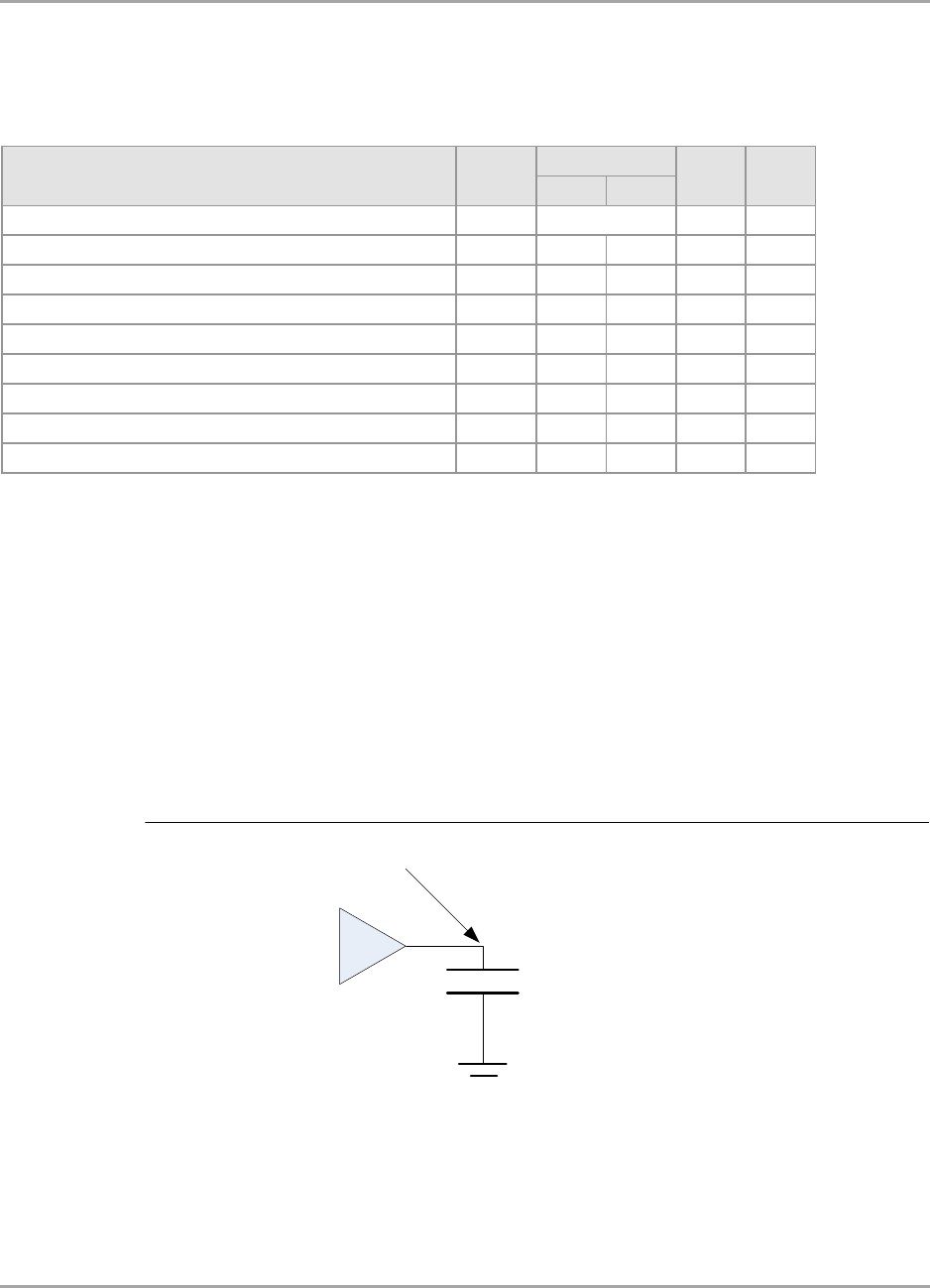
8.6.12.2 SPI (Master Mode) Test Circuit
Figure 34: SPI (Master Mode) Test Circuit
Min Max
SCLK clock frequency fCK MHz 3
SCLK high time tCH 0.46 - tCK 1
SCLK low time tCL 0.46 - tCK 1
SCLK slew rate tSR 0.5 - V/ns 1
Data out valid relative to SCLK falling edge tDOV -2.5 2.5 ns 1
CS active before SCLK rising edge tCSB 8.0 - ns 1
CS not active after SCLK rising edge tCSA 8.0 - ns 1
Data in setup time relative to SCLK rising edge tSU 0.2 - tCK 2
Data in hold time relative to SCLK rising edge tHD 5.0 - ns 2
Note s:
General comment: All values were measured from 0.3*vddio to 0.7*vddio, unless otherw ise specified.
General comment: tCK = 1/fCK.
1. For all signals, the load is CL = 10 pF.
2. Defined from vddio/2 to vddio/2.
3. See "Reference Clocks" table for more details.
See Note 3
Note s
SPI
Description Symbol Units
CL
Test Point