


Electrical Specifications
AC Electrical Specifications
Copyright © 2008 Marvell Doc. No. MV-S104859-U0 Rev. E
December 2, 2008, Preliminary Document Classification: Proprietary Information Page 115
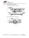
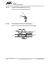
8.6.14 Transport Stream (TS) Interface AC Timing
8.6.14.1 Transport Stream Interface AC Timing Table
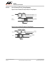
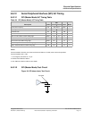
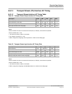
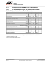
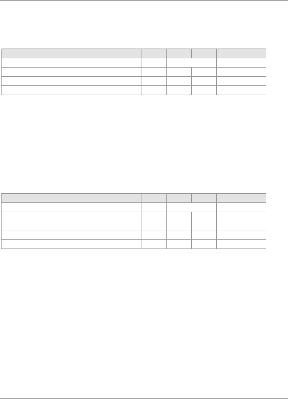
Table 62: Transport Stream Output Interface AC Timing Table
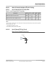
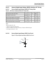
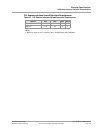
Table 63: Transport Stream Input Interface AC Timing Table
Description Symbol Min Max Units Notes
Clock frequency fCK MHz 1
Clock minimum low level w idth tLOW 0.4 0.6 tCK 2
Clock minimum high level w idth tHIGH 0.4 0.6 tCK 2
Data output valid after Clock rising edge tOV 0.4 0.6 tCK 2, 3
Notes:
General comment: All values were measured from VIL(max) to VIH(min), unless otherw ise specified.
General comment: tCK = 1/fCK.
1. See "Reference Clocks" table for more details.
2. For all signals, the load is CL = 5 pF.
3. When configured to falling edge, the tOV parameter is relative to Clock falling edge.
See note 1
Description Symbol Min Max Units Notes
Clock frequency fCK MHz 1
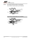
Clock minimum low level w idth tLOW 0.35 0.65 tCK -
Clock minimum high level w idth tHIGH 0.35 0.65 tCK -
Data input setup time relative to Clock rising edge tSU 0.30 - tCK 2
Data input setup time relative to Clock rising edge tHD 0.30 - tCK 2
Notes:
General comment: All values were measured from VIL(max) to VIH(min), unless otherw ise specified.
General comment: tCK = 1/fCK.
1. See "Reference Clocks" table for more details.
2. When configured to falling edge, the tSU/tHD parameters are relative to Clock falling edge.
See note 1