System Power Up/Down and Reset Settings
Hardware Reset
Copyright © 2008 Marvell Doc. No. MV-S104859-U0 Rev. E
December 2, 2008, Preliminary Document Classification: Proprietary Information Page 65
6.2.1 Reset Out Signal
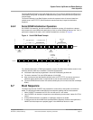
The device has an optional SYSRST_OUTn output signal, multiplexed on an MPP pin, that is used
as a reset request from the device to the board reset logic. SYSRST_OUTn is the default option for
that MPP pin.
This signal is asserted low for 20 ms, when one of the following maskable events occurs:
Received hot reset indication from the PCI Express link (only relevant when used as a PCI
Express endpoint), and bit <PexRstOutEn> is set to 1 in the RSTOUTn Mask Register (see the
Reset register section of the 88F6180, 88F6190, 88F6192, and 88F6281 Functional
Specifications).
PCI Express link failure (only relevant when used as a PCI Express endpoint), and bit
<PexRstOutEn> is set to 1 in the RSTOUTn Mask Register.
Watchdog timer expiration and bit <WDRstOutEn> is set to 1 in the RSTOUTn Mask Register.
Bit <SystemSoftRst> is set to 1 in System Soft Reset Register and bit <SoftRstOutEn> is set
to 1 in RSTOUTn Mask Register.
This signal is asserted low for 20 ms, when one of the following non-maskable events occurs:
Power on reset (The device includes a power-on-reset (POR) circuit for VDD power.)
SYSRST_OUTn is asserted low as long as the MRn input signal is asserted low and for an
additional 20 ms after MRn de-assertion. (This is useful for implementations that include a
manual reset button.)
6.2.2 Power On Reset (POR)
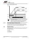
The SYSRST_OUTn output signal is asserted low for 20 ms, when the power-on-reset (POR) circuit
is triggered.
POR is triggered when VDD power up (digital core voltage) reaches a VDD threshold (threshold
maximum value 0.8V).
Hysteresis: Another trigger will only occur after the power first drops to 50 mV, and then a power up
occurs.
6.2.3 SYSRSTn Duration Counter
When SYSRSTn is asserted low, a SYSRSTn duration counter is running.
The counter clock is the 25 MHz reference clock.
It is a 29-bit counter, yielding a maximum counting duration of 2^29/25 MHz (21.4 seconds).
The host software can read the counter value and reset the counter.
When the counter reach its maximum value, it remains at this value until counter reset is
triggered by software.
Note
Reset (SYSRSTn signal) must be active for a minimum length of 5 ms. core power, I/O
power, and analog power must be stable (VDD +/- 5%) during that time and onward.
Note
The SYSRSTn duration counter is useful for implementing manufacturer/factory reset.
Upon a long reset assertion, greater than a pre-configured threshold, the host software
may reset all settings to the factory default values.


