System Power Up/Down and Reset Settings
Pins Sample Configuration
Copyright © 2008 Marvell Doc. No. MV-S104859-U0 Rev. E
December 2, 2008, Preliminary Document Classification: Proprietary Information Page 69
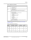
GE_TXD[2:0] Boot Device
0x0 = Reserved
0x1 = Reserved
0x2 = Boot from SPI flash (SPI_CSn on MPP[7])
0x3 = Reserved
0x4 = Boot from SPI flash (SPI_CSn on MPP[0])
0x5 = Boot from NAND flash
0x6 = Boot from SATA
0x7 = Boot from the PCI Express port
NOTE:
• Internally pulled to 0x4.
• Only SPI signals configured on pins MPP[3:0] or on pins MPP[7] and MPP[3:1] can be used for
booting from SPI.
SPI signals that are multiplexed on other MPPs can only be used after booting (see Section 4.1,
Multi-Purpose Pins Functional Summary, on page 51).
• When GE_TXD[2:0] is set to 0x4, MPP[3:0] wake up as SPI signals.
• When GE_TXD[2:0] is set to 0x2, MPP[7] and MPP[3:1] wake up as SPI signals.
• When GE_TXD[2:0] is set to 0x5, MPP[5:0] and MPP[19:18] wake up as NAND Flash signals.
• For a more detailed description of the bootROM, see the BootROM section in the 88F6180,
88F6190, 88F6192, and 88F6281 Functional Specifications.
• For a more detailed description of the boot from SPI flash or NAND flash, see the SPI Interface
and NAND Flash Interface sections in the 88F6180, 88F6190, 88F6192, and 88F6281 Functional
Specifications.
• There is an option to boot from UART when GE_TXD[2:0] = 0x2–0x7. For a more detailed
description of the boot from UART, see the BootROM section in the 88F6180, 88F6190,
88F6192, and 88F6281 Functional Specifications.
GE_TXD[3] SSCG Disable
0 = Enable
1 = Disable
NOTE: Internally pulled to 0x1.
GE_MDC PCI Express Clock (100 MHz Differential Clock) Configuration
0x0 = The device use external source for PCI Express clock. Pins PEX_CLK_P/PEX_CLK_N are
inputs.
0x1 = The device uses internal generated clock for PCI Express clock. Pins
PEX_CLK_P/PEX_CLK_N pins are outputs, driving out the PCI Express differential clock.
NOTE: Internally pulled to 0x1.
GE_TXCTL Used for internal testing
Must be 0x0 during reset. Either leave the signal floating (internally pulled down to 0x0) or pull the signal to
0x0 during reset.
MPP[7] Reserved
Must be 0x1 during reset. Either leave the signal floating (internally pulled up to 0x1) or pull the signal
to 0x1 during reset.
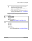
Table 32: Reset Configuration (Continued)
Pin Configuration Function


