


Electrical Specifications (Preliminary)
Thermal Power Dissipation
Copyright © 2008 Marvell Doc. No. MV-S104859-U0 Rev. E
December 2, 2008, Preliminary Document Classification: Proprietary Information Page 79
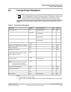
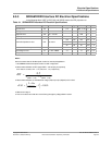
8.3 Thermal Power Dissipation
The purpose of the Thermal Power Dissipation table is to support system engineering in thermal
design.
.
Notes:
1. The values are for nominal voltage.
2. Power in mW is calculated using the typical recommended VDDIO specification for each power
rail.
Note
Before designing a system, Marvell recommends reading application note AN-63:
Thermal Management for Marvell Technology Products. This application note presents
basic concepts of thermal management for integrated circuits (ICs) and includes
guidelines to ensure optimal operating conditions for Marvell Technology's products.
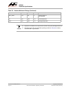
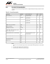
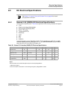
Table 37: Thermal Power Dissipation
Interface Symbol Test Conditions Typ Units
Core (VDD 1.0V) P
VDD
TCLK @ 200 MHz 280 mW
Embedded CPU (VDD_CPU 1.1V) P
VDD_CPU
CPU @ 1000 MHz,
L2 @ 333 MHz
790 mW
CPU @ 1200 MHz,
L2 @ 400 MHz
870 mW
CPU @ 1500 MHz,
L2 @ 500 MHz
1050 mW
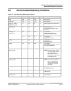
RGMII 1.8V interface P
RGMII
30 mW
RGMII (10/100 RGMII only) 3.3V interface P
RGMII
50 mW
GMII 3.3V interface P
GMII
50 mW
MII/MMII 3.3V interface P
MII
10 mW
Miscellaneous interfaces
(JTAG, TWSI, UART, NAND flash, Audio,
SDIO, TDM, TS, and SPI)
P
MISC
50 mW
DDR2 SDRAM interface (On-board,
16-bit, 400 MHz)
P
DDR2
Four on board devices, 75 ohm
ODT termination
250 mW
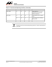
eFuse during Burning mode
NOTE: Since the eFuse burn is performed
only once, there is no thermal
effect after the burn has finished.
P
FUSE
50 mW
eFuse during Reading mode P
FUSE
25 mW
PCI Express interface P
PEX
100 mW
USB interface P
USB
120 mW
SATA interface P
SATA
Both SATA ports 410 mW