


Appendix D Register-Level Programming
National Instruments Corporation D-31 PC-LPM-16/PnP User Manual
after getting the required number of conversions. The number of
conversions in a single data acquisition operation in this case is
unlimited. Counter 0 is clocked by a 1 MHz clock upon start up.
Each of these programming steps is explained as follows.
1. Select the Analog Input Channel.
Write to Command Register 1 to select the analog input channel.
The SCANEN* bit must be set for data acquisition operations on a
single channel. See the Command Register 1 bit descriptions earlier
in this appendix for analog input channel bit patterns.
Write to Command Register 1 only when the analog input channel,
scanning mode, or interrupt mode needs to be changed.
To enable the data acquisition operation, clear the CALEN bit of
Command Register 2.
2. Program the Sample-Interval Counter (counter 0).
Counter 0 of the MSM82C53 counter/timer is used as the sample-
interval counter. A low-to-high transition on OUT0 (counter 0
output) initiates a conversion. You can program counter 0 to
generate a pulse once every N µs. N is referred to as the sample
interval; that is, the time between successive A/D conversions.
N can be between 20 and 65,535. The sample interval is equal to the
period of the timebase clock used by counter 0 multiplied by N.
A 1 MHz clock is internally connected to CLK0 (the clock used by
counter 0).
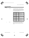
Use the following programming sequence to program counter 0, the
sample-interval counter. All writes are 8-bit write operations. All
values given are hexadecimal.
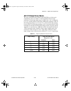
a. Write 34 to the Counter Mode Register (select counter 0,
mode 2).
b. Write the least significant byte of the sample interval to the
Counter 0 Data Register.
c. In Step a., writing to the Counter Mode Register forces OUT0
to high. To finish programming counter 0, you must also write
the most significant byte. However, this writing starts the
counting, so perform this writing in step 4.
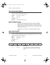
3. Clear the A/D circuitry.
Before starting the data acquisition operation, empty the A/D FIFO
to clear out any old A/D conversion results. You must do this after
programming the counters in case any spurious edges were caused
a.Book : l.Appendix D Page 31 Wednesday, November 20, 1996 6:36 PM