


Appendix D Register-Level Programming
National Instruments Corporation D-27 PC-LPM-16/PnP User Manual
This sequence leaves the PC-LPM-16/PnP circuitry in the following
state:
• Counter 0 output is high.
• Multichannel scan is disabled.
• All interrupts are disabled.
• Analog input circuitry is initialized to channel 0.
• The A/D FIFO is cleared.
For additional details concerning the MSM82C53 counter/timer, see
Appendix B, MSM82C53 Data Sheet.
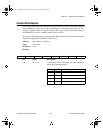
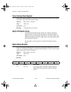
Programming the A/D Calibration
The ADC is a self-calibration converter and a self-calibration cycle
adjusts positive linearity and full-scale errors. To start a self-calibration
cycle, perform the following steps:
1. Write 01 to Command Register 2 to enable the self-calibration
cycle.
2. Read Command Register 2 to start the self-calibration cycle and
ignore the result of the reading.
3. Read the Status Register and check the CONVPROG bit. After
starting the self-calibration, checking this bit can detect the
completion of the self-calibration cycle. A one in this bit indicates
the calibration is in progress, and zero indicates the completion of
the calibration.
4. After the self-calibration cycle, write 0 to Command Register 2 to
enable the A/D conversion.
The ADC should be calibrated after the reference has stabilized,
although you may recalibrate it later to adjust to changes over time or
temperature.
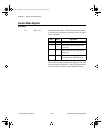
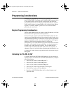
Programming the Analog Input Circuitry
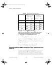
This section describes the analog input circuitry programming sequence
and explains the A/D conversion results and how to clear the analog
input circuitry.
a.Book : l.Appendix D Page 27 Wednesday, November 20, 1996 6:36 PM