


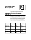
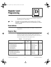
Appendix C Using Your PC-LPM-16 (Non-PnP) Board
National Instruments Corporation C-9 PC-LPM-16/PnP User Manual
Note:
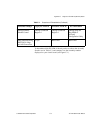
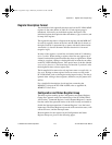
Base I/O address values hex 000 through 0FF are reserved for system use.
Base I/O address values hex 100 through 3FF are available on the I/O
channel.
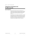
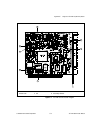
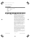
Interrupt Selection
The PC-LPM-16 connects to any one of the six interrupt lines of the
computer I/O channel. A jumper selects the interrupt line on one of the
double rows of pins located above the I/O slot edge connector on the
PC-LPM-16 (see Figure C-1). To use the PC-LPM-16 interrupt
capability, select an interrupt line and place the jumper in the
appropriate position to enable that particular interrupt line.
The interrupt lines that the PC-LPM-16 hardware supports are
IRQ<3..7>, and IRQ9.
Note:
Using interrupt line 6 is not recommended. The diskette drive controller
uses interrupt line 6 on most IBM PC and compatible computers.
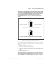
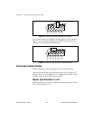
After you select an interrupt level, place the interrupt jumper on the
appropriate pins to enable the interrupt line.
The interrupt jumper setting is
W3
. The default interrupt line is IRQ5,
which you select by placing the jumper on the pins in row 5, as shown
in Figure C-3. To change to another line, remove the jumper from IRQ5
and place it on the new pins.
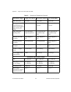
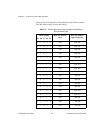
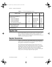
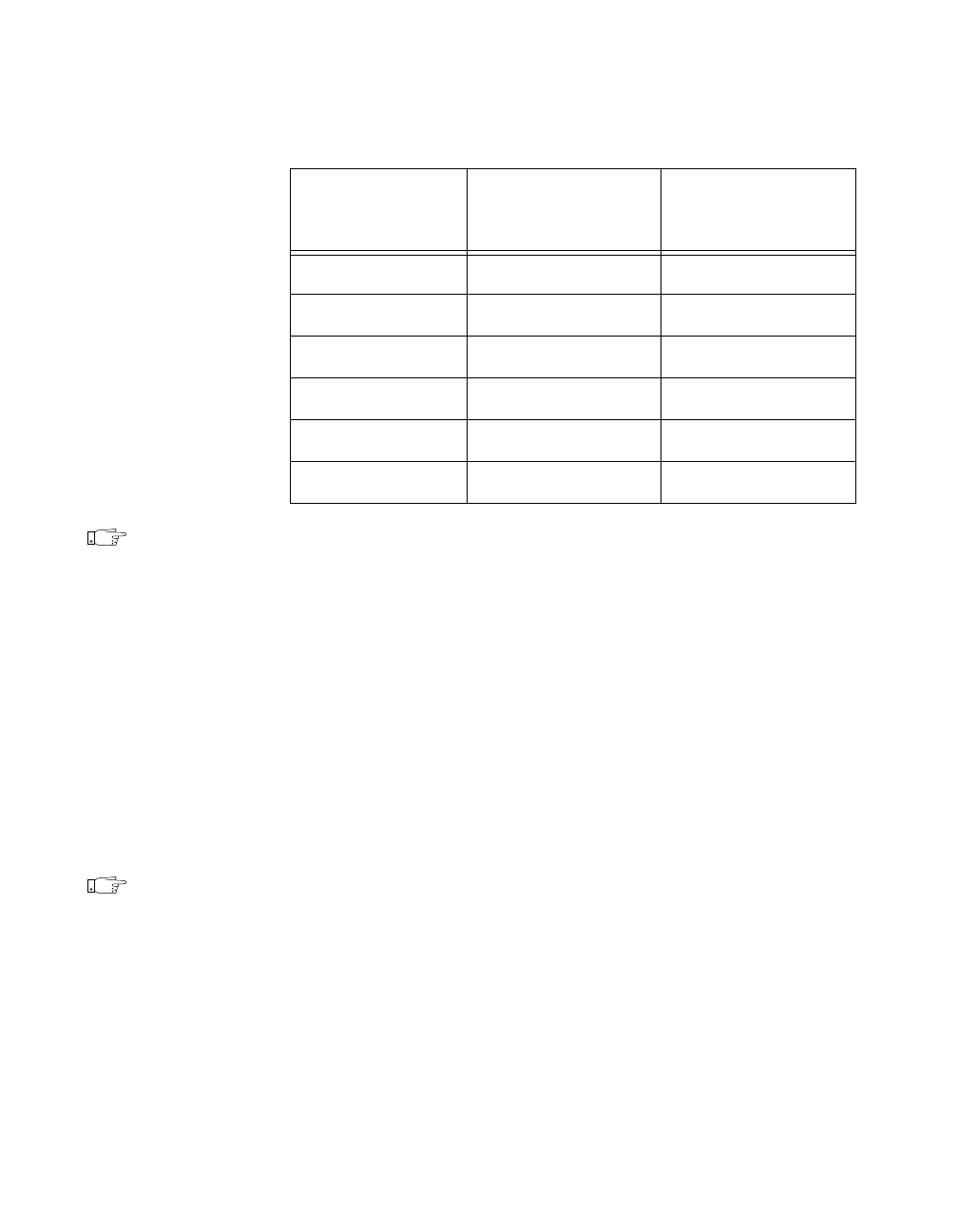
1 1 0 1 0 340 340–34F
1 1 0 1 1 360 360–36F
1 1 1 0 0 380 380–38F
1 1 1 0 1 3A0 3A0–3AF
1 1 1 1 0 3C0 3C0–3CF
1 1 1 1 1 3E0 3E0–3EF
Table C-3.
Switch Settings with Corresponding Base I/O Address and
Base I/O Address Space (Continued)
Switch Setting
Base I/O Address
(hex)
Base I/O Address
Space Used (hex)
A9 A8 A7 A6 A5