


Chapter 4 Signal Connections
PC-LPM-16/PnP User Manual 4-8
National Instruments Corporation
fuse in series. Both fuses are self-resetting; simply remove the circuit
causing the heavy current load and the fuse will reset itself.
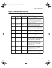
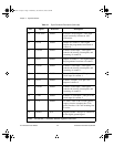
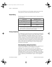
Power Rating
The following table shows the maximum current for each power line at
the I/O connector.
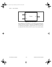
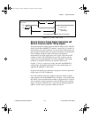
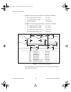
Timing Connections
Pins 38 through 48 of the I/O connector are connections for timing I/O
signals. The timing input and output of the PC-LPM-16PnP is designed
around an MSM82C53 counter/timer integrated circuit. All three
counters of the circuit are available at the I/O connector. One of these
counters, counter 0, is used for data acquisition timing. Pin 39 carries
an external signal that can be used for data acquisition timing in place
of counter 0. Pins 38 and 41 through 48 carry general-purpose timing
signals. These signals are explained in the
General-Purpose Timing
Signal Connections and General-Purpose Counter Timing Signals
section later in this chapter.
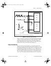
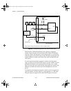
Data Acquisition Timing Connections
Counter 0 on the MSM82C53 counter/timer is used as a sample-interval
counter in timed A/D conversions. In addition to counter 0,
EXTCONV* can externally time conversions. See Appendix D,
Register-Level Programming
, for the programming sequence needed to
enable this input. Figure 4-4 shows the timing requirements for the
EXTCONV* input. An A/D conversion is initiated by a rising edge on
the EXTCONV*. The data from this conversion is latched into the FIFO
memory within 20
µ
s. The EXTCONV* input is a TTL-compatible
signal.
Power Line
Maximum Current
+5 V (self-resetting fuse at 1.0 A)
1.0 A*
+12 V (self-resetting fuse at 0.5 A) 0.5 A*
-12 V 5.0 mA
* The actual current available from these signals may be less, depending
on your computer. Notice also that any current drawn from these lines
adds to the power requirements from the computer.
a.Book : h.chapter 4 Page 8 Wednesday, November 20, 1996 6:36 PM