


Appendix D Register-Level Programming
PC-LPM-16/PnP User Manual D-16
National Instruments Corporation
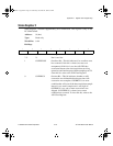
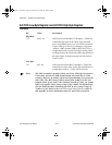
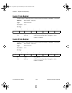
A/D FIFO Low-Byte Register and A/D FIFO High-Byte Register
(Continued)
Bit Name Description
High Byte
7–0 D<15..8> A/D Conversion Data Bits 15 through 8—These bits
contain the high byte of the 16-bit, sign-extended
two’s complement result of a 13-bit A/D conversion.
Values made up of D<15..0>, therefore, range from
-4096 to +4095 decimal (F000 to 0FFF hex). Two’s
complement mode is useful for bipolar analog input
readings because the values read reflect the polarity of
the input signal. In unipolar mode only the positive
value is used.
Low Byte
7–0 D<7..0> A/D Conversion Data Bits 7 through 0—These bits
contain the low byte of the 16-bit, sign-extended two’s
complement result of a 12-bit A/D conversion.
Note:
The ADC resolution is actually 13 bits, not 12 bits. NI-DAQ only returns a
12-bit value, and the PC-LPM-16/PnP boards are tested only to 12-bit
accuracy. However, by writing register-level programming, you can use the
full 13 bits. The ADC always returns values from -4,096 to +4,095. For
unipolar mode, if you want 12-bit resolution instead of 13-bit, you should
ignore any negative value, giving a range of 0 to +4.095. For bipolar mode,
you can divide the value returned by the ADC by two, giving a range of
-2,048 to +2.047. Refer to the
A/D FIFO Output Binary Modes
section in
this appendix for more information about 13- and 12-bit conversions.
a.Book : l.Appendix D Page 16 Wednesday, November 20, 1996 6:36 PM