


Chapter 4 Signal Connections
National Instruments Corporation 4-7 PC-LPM-16/PnP User Manual
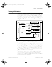
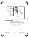
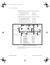
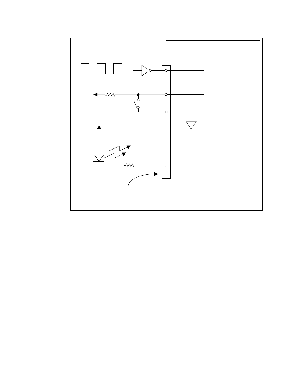
Figure 4-3.
Analog Input Signal Connections
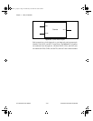
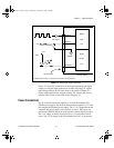
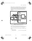
Figure 4-3 shows the connections of the digital input port and digital
output port. Digital input applications include receiving TTL signals
and sensing external device states such as the switch in Figure 4-3.
Digital output applications include sending TTL signals and driving
external devices such as the LED shown in Figure 4-3.
Power Connections
Pin 49 of the I/O connector supplies +5 V from the computer I/O
channel power supply. Pin 20 of the I/O connector supplies +12 V from
the computer I/O channel power supply. The -12 V is supplied from the
computer I/O power supply with a resistor in series. These pins are
referenced to DGND and can be used to power external digital circuitry.
The +5 V supply at the I/O connector has a 1.0 A protection fuse in
series. The +12 V supply at the I/O connector has a 0.5 A protection
TTL Signal
Digital
Input
Port
Digital
Output
Port
22 DIN 0
19
DGND
I/O Connector
PC-LPM-16PnP
LED
+5 V
+5 V
29 DIN 7
30 DOUT 0
Debounced Switch*
*Complex switch circuitry is not shown here in order to simplify the figure.
a.Book : h.chapter 4 Page 7 Wednesday, November 20, 1996 6:36 PM